
De un vistazo – Quick look
MATERIAL Y PIEZAS
MEDIA & PARTS:
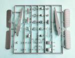
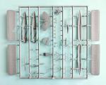
- Plástico inyectado (76 piezas), plástico transparente (2 piezas), fotograbado (17 piezas).
- Injected plastic (76 parts), clear plastic (2 parts), photo-etched (17 parts).
CALCAS – DECALS:
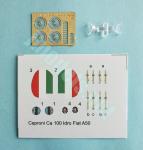
- Insignias italianas y cinturones. Apariencia fina y buena saturación de color. El soporte es ligeramente excesivo salvo en los arneses.
- Italian tail markings and badges plus belts. Thin appearance with good color saturation. The carrier film is a bit excessive except on the belts.
OPCIONES – OPTIONS:
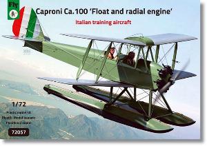
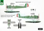
- Caproni Ca.100 con motor Fiat A.50. Fuerza Aérea Italiana. Italia, años 30.
- Caproni Ca.100 with Fiat A.50 engine. Italian Air Force. Italy, 1930s.
INSTRUCCIONES – INSTRUCTIONS:
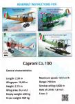
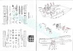
- Folleto de tamaño A5 de 8 páginas impreso en color en papel brillante. Contiene datos técnicos del avión, un plano numerado de piezas y 14 secuencias de montaje sin numerar. La cara trasera de la caja muestra perfiles en color y una relación de tonos genéricos.
- 8-page A5 booklet printed in color on glossy paper. It shows technical data about the aircraft, a numbered parts diagram and 14 assembly sequences without numbers. The back side of the box contains profiles in color and a short list of generic paints.
LO MEJOR – THE BEST:
- Buen detalle general. Carlinga. Alternativas de montaje.
- Overall nicely detailed. Nice cockpit. Assembly choices.
LO PEOR – THE WORST:
- Slats mejorables. Referencias de color. Opciones de pintura (en esta caja).
- Improvable wing slats. Poor color references. Paint options (in this box).
VALORACIÓN – CONCLUSION:
- Primera maqueta de plástico de este avión. Detalle bastante acertado y montaje aparentemente sin sorpresas para el modelista con mediana experiencia en maquetas de serie limitada. Recomendable a los seguidores de la aviación de entreguerras.
- First plastic kit of this aircraft. It has a quite accurate detail and seems to pose no challenge for the modeller used to building short-run kits. Recommended to fans of interwar aircraft.

La maqueta
Hace unos meses Fly sacó la primera maqueta de plástico del Caproni Ca.100 en cuatro versiones que combinan diferentes motores (radial y en línea) con distintos tipos de trenes (ruedas y flotadores). Las cuatro cajas contienen las mismas piezas y por tanto permiten construir cualquiera de las versiones, aunque las calcas son diferentes. Hasta ahora las maquetas de este avión eran producidas en resina por Legato a escala 1/48 y por esta marca y la polaca Choroszy Modelbud a escala 1/72.
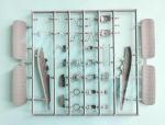
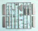
La caja contiene dos bastidores de piezas, un pequeño bastidor transparente, una lámina de fotograbados, las calcas y las instrucciones. Todo ello está bien protegido con bolsas independientes para las piezas transparentes, los fotograbados y las calcas. El plástico no está mal de dureza, aunque parece un poco rígido. Casi en su totalidad las piezas están libres de imperfecciones y rebabas. Las pocas marcas están situadas en los lados internos de la carlinga delantera sin afectar al detalle ni ser evidentes. El motor radial tiene lineas de molde y algunas mínimas rebabas que limpiar.
Dado que el molde es compartido por cuatro versiones, hay múltiples opciones de montaje en la maqueta. Así, tenemos diferencias en las alas, ruedas y timones que describiré más abajo.
La maqueta representa uno de los entrenadores italianos más comunes de los años 30, del que se fabricaron unos 700 ejemplares y se exportó a varios países (Portugal y Bulgaria entre otros) y se fabricó con licencia en Perú y Bulgaria. También tuvo su mercado civil y fue empleado por escuelas de vuelo y particulares. El Ca.100 tenía bastante parecido con el popular de Havilland DH.60 Moth, pero las alas tenían configuración de sesquiplano invertido y las superficies de cola estaban modificadas. Al igual que el Moth, llevó una gran cantidad de motores distintos, tanto radiales como en línea. La versión específica de esta caja es la denominada Ca.100 Idro, de la que Macchi produjo 30 unidades con flotadores. Dos aparatos participaron en la Guerra Civil Española.
Carlinga
Los lados internos del fuselaje tienen moldeada la estructura con nitidez. No hay propiamente un suelo, sino que la base de las palancas de control va situada entre las dos mitades del fuselaje. Sobre esta base van dos asientos con cinturones de calca y para completar el interior un panel que cubre todo el hueco delantero, un panel trasero y otro entre los dos puestos, dos juegos de pedales y los paneles de instrumentos, de tamaño y detalle diferente para el instructor y el alumno, ambos con los instrumentos finamente grabados. Los parabrisas, también distintos, son finos, pero no demasiado transparentes.
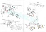
Fuselaje y motor
Las mitades del fuselaje están grabadas con ciertos detalles, como los estribos laterales y el compartimento de equipaje en el lado izquierdo. El morro está diseñado para montar la versión con motor en línea. El motor sólo está parcialmente detallado y dispone de dos carenas laterales, la parte superior del motor con las pequeñas cabezas de los cilindros y una línea de escapes separados más un frontal que muestra el primer cilindro y la caja de engranajes de la hélice. Pese al diminuto tamaño, el detalle está bien definido. Una vez instalado en el fuselaje, hay que montar el frontal del capó, correctamente detallado con las tomas y la hélice, que es más ancha y un poco más corta que la del motor radial. Las palas se pueden afinar un poco para hacerlas más realistas.
Para construir la versión con motor radial, que es la pertinente en esta caja, es necesario cortar diagonalmente la parte delantera del fuselaje. La línea de corte está bien marcada en los lados internos, pero no sobre la base. Hay que medir bien el corte de la base porque está demasiado próximo al rebaje para pegar el tren de aterrizaje y al panel anterior de la carlinga. El carenado del motor también consta de dos piezas y un frontal donde pegar el motor radial. El motor no es nada especial porque está detallado con unos alzaválvulas demasiado gruesos sobre el frontal. Hay un fino colector por detrás y los escapes aparte, el principal de ellos más largo situado por debajo. Por delante hay que instalar el carenado frontal y la hélice, que también se puede mejorar en finura. Bajo el morro hay que instalar el refrigerador de aceite, cuya posición está marcada en las instrucciones en caracteres microscópicos.
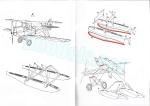
Alas y cola
Las alas tienen doble opción, con o sin ranuras en los bordes de ataque. La alternativa aplicable en esta versión está indicada en la parte trasera de la caja. El entelado en las superficies me parece convincente y bien representado. Los timones están grabados con nitidez y los slats poseen un relieve acertado, con las bisagras moldeadas en la cara inferior. Realmente los slats deberían venir separados para ponerlos en posición abierta al estar el avión parado, ya que eran manuales y se controlaban con los flaps.
Los planos superiores, en este caso de menor longitud que los inferiores, están unidos con una lengüeta que sirve para sustentar el depósito de combustible, dividido en mitades y detallado en ambas. Los soportes intermedios están perfilados, pero los posteriores son bastante finos y delicados.
Los planos inferiores van pegados por debajo de lengüetas muy cortas a los lados del fuselaje. Las caras inferiores llevan actuadores de plástico para los timones. Las puntas no tienen las luces, pero en las fotos de este avión casi nunca se ven instaladas. Las instrucciones incluyen una ilustración para situar las riostras entre los planos.
La cola viene separada en dos piezas. La deriva y el timón vertical están moldeados en una pieza, con el entelado bien ejecutado. La luz de cola y el soporte del cable actuador también están representados. Para mejorarlo, el soporte puede reemplazarse por un diminuto fotograbado. Las superficies horizontales muestran idéntico detalle, con dos actuadores sustituibles por fotograbados, dos soportes inferiores y el patín de cola para la versión de ruedas.
Tren de aterrizaje
Los flotadores se componen de dos piezas longitudinales. La superior muestra un adecuado detalle en relieve y los timones separados. Hay dos alternativas para los timones, de formas triangulares o cuadradas, pero observando los perfiles de la caja los correctos en esta versión son los primeros. La estructura de soporte de los flotadores consta de cinco piezas, dos de ellas unen los flotadores transversalmente y los demás van unidos al fuselaje. El delantero va pegado en un rebaje justo por debajo del morro. Las instrucciones incluyen un diagrama para arriostrar los soportes.
El tren de ruedas tiene el conjunto de soportes separados en dos piezas. Las ruedas también tienen doble alternativa. Una de ellas tiene el neumático detallado con radios de fotograbado y en la otra las ruedas tienen tapacubos sencillos y neumáticos bien marcados.
Calcas
La hoja contiene insignias italianas y los cinturones que tienen apariencia fina y buena saturación de color. El soporte es un poco excesivo, salvo en los arneses.
Instrucciones
El folleto tiene un tamaño A5 y consta de ocho páginas impresas en color sobre papel brillante. Contiene datos técnicos del avión, un plano numerado de piezas y 14 secuencias de montaje sin numerar. La cara trasera de la caja muestra perfiles en color y una relación de tonos genéricos. Aunque las vistas explosionadas del montaje son bastante claras, el folleto carece de referencias para pintar la carlinga.
Valoración
Este es el primer Caproncino en plástico que nos ha librado de tener que hacerlo de resina como hasta ahora. Felizmente, a Fly se le ha ocurrido sacarlo en múltiples versiones de diferentes países, aunque esta caja es la que menos ofrece. Se podría haber incluido alguna opción portuguesa o búlgara para completar el abanico de posibilidades de nacionalidades y opciones de pintura.
El detalle está bien representado, tal vez gracias a que Fly se ha fijado en los varios aparatos aún conservados en museos (uno de ellos aún vuela en el Lago Como en Italia). El montaje no parece nada extraordinario para quienes afronten esta maqueta con la experiencia pertinente en biplanos de serie limitada.◊

The kit
A few months ago Fly released the first plastic kit of the Caproni Ca.100 in four versions combining different engines (radial and inline) with different types of undercarriage (wheels and floats). The four boxes launched contain the same parts and therefore they allow to build any of the versions with the obvious change in the decals. Until now we only had 1/48 and 1/72 resin kits from Legato and the Polish Choroszy Modelbud.
The box contains two sprues of parts, a small sprue for the clear parts, a sheet of etched parts, the decals and the instructions. All of this is well protected with separate bags for the clear parts, the photo-etched parts and the decals. Plastic is not hard but it does seem a little stiff. Parts are free from blemishes and most of them from flash too. There are only positive marks on the cockpit walls that do not affect detail and are not evident either. The radial engine has seam lines and some minimal flash to clean up.
Since the tooling is shared by the four Ca.100 versions, we have multiple assembly options. So, we have differences in the wings, wheels and float rudders which I will describe below.
The kit represents one of the most common Italian trainers of the 1930s. About 700 examples were built and the type was exported to several countries (Portugal and Austria among others) and manufactured under licence in Peru and Bulgaria. It also had a small civil market and was used by flight schools and private owners. The Ca.100 was quite similar to the popular de Havilland DH.60 Moth, but the wings had an inverted sesquiplane configuration and the tail surfaces were modified. Like the Moth, it carried a wide number of different engines, both radial and inline. The specific version in this kit is the so-called Ca.100 Idro (floatplane), of which Macchi produced 30 units with floats. Two aircraft participated in the Spanish Civil War.
Cockpit
The cockpit sides are moulded with the raised interior structure cleanly represented. There is no actual floor, but the base of the control sticks is attached between the two fuselage halves. The seats, provided with decal belts, are glued on the base. The rest of the cockpit comprises a bulkhead covering the front gap, a rear bulkhead plus another in between the cabins, two sets of pedals and the instrument panels, rendered with different size and detail for the instructor and the student, and both with finely engraved instruments. The windscreens, also different, are thin but not too transparent.
Fuselage and engine
The fuselage halves show some detail, such as the foot holds and the luggage compartment on the left side. The nose is designed to build the inline engine version. The engine is only partially detailed and has two side fairings, the top of the engine with the small cylinder heads, a row of separate exhausts plus a front piece showing the first cylinder and the propeller crankcase. Despite the small size, detail is sharp. Once the engine is attached to the fuselage, you add the cowling front, which is correctly detailed with the air intakes and the propeller. This is wider and slightly shorter than that in the radial engine. The blades can be thinned a little for a more realistic look.
To build the radial engine version, which is the topic of this box, it is necessary to cut diagonally the fuselage front. The cutting line is well marked on the fuselage interior sides but not on the belly. The cut of the belly needs some care because it is too close to the recess necessary for attaching the landing gear / floats and the front cockpit bulkhead. The engine fairing also consists of two pieces and a front where the radial engine is glued. The engine is nothing to write home about because it is detailed with too thick valve tappets on the front. There is a thin exhaust manifold at the back, short exhaust pipes attached to the cylinder heads and a longer main exhaust pipe under the engine. The engine front is detailed with a fairing and the propeller, which also needs some thinning. Under the nose you add the oil cooler by drilling holes in the fuselage, but the instructions show the measures in microscopic characters.
Wings and tail
The wings have a choice for leading edges with or without slats. The option applicable to this version is indicated on the back of the box. The fabric on the surfaces seems convincing and nicely represented. The flaps are clearly engraved and the slats are moulded a bit raised on the plastic surface with the hinges moulded on the lower side. The slats should really come separated to pose them in the open position when the plane is stopped, since they were manually controlled with the flaps.
The upper wing pieces are joined with a tab to hold the main fuel tank halves in between. The tanks halves show some raised detail. The cabane V-struts are good, but the rear single struts are quite thin and brittle.
The lower wings are glued under very short tabs on the fuselage sides. The lower sides have plastic actuators for the flaps. The tips do not have the lights, but the pictures of this aircraft show they were rarely installed. The instructions include an illustration for bracing the interplane struts.
The tail comes separated in two pieces. The fin and vertical rudder are moulded in one piece, with a nice representation of the fabric surface. The tail light and control horn are also included. You have the alternative to replace the rudder control horn with a tiny photo-etched part. The horizontal surfaces show identical detail, with two horns replaceable with PE parts, two tailplane brace struts and a tail skid for the wheeled version.
Undercarriage
The floats are separated in two pieces with the top surfaces showing some raised detail and separate rudders. These have triangular or square alternative pieces but according to the profiles on the box, the correct choice for this version are the first ones. The support structure of the floats consists of five pieces, two of them join the floats transversely and the others are attached to the fuselage. The front strut is glued into a recess just below the fuselage nose. Also in this case, the instructions include a diagram for bracing the supports.
The wheeled version include two pieces for the supports. You can choose either a set of spoked wheels detailed with etched pieces on both sides of the tires or an alternative with simple hubcaps and well engraved tires.
Decals
The sheet contains Italian markings and badges and the seat belts. Decals have a fine appearance and good color saturation. The carrier film is a bit excessive, except for the belts.
Instructions
They come in an 8-page A5 booklet printed in color on glossy paper. It contains technical data of the aircraft, a numbered parts plan and 14 unnumbered assembly sequences. The back of the box shows color profiles and a list of generic paints. Although the exploded assembly views are quite clear, the booklet lacks references for painting the cockpit.
Conclusion
This is the first Caproncino in plastic, so those modellers who are not very keen on resins will be pleased. Fortunately, Fly has come up with the idea of releasing it in multiple versions from different countries, although this specific box is the poorest in this sense. A Portuguese and a Bulgarian choice could have completed the range of nationalities and painting options.
Overall detail is fine, perhaps thanks to Fly’s study of the various Ca.100s still preserved in museums (one of them still flies on Lake Como in Italy). Assembly does not seem anything extraordinary for those who build this kit with the necessary experience in short-run biplanes.◊
Publicado – Published: 10 / 2024
©www.jmodels.net

Debe estar conectado para enviar un comentario.