
De un vistazo – Quick look
MATERIAL Y PIEZAS
MEDIA & PARTS:
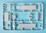
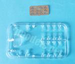
- Plástico inyectado (81 piezas), plástico transparente (18 piezas), fotograbado (12 piezas).
- Injected plastic (81 parts), clear plastic (18 parts), photo-etched (12 parts).
CALCAS – DECALS:
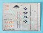
- Insignias norteamericanas, panel antirreflectante del morro, líneas y matrículas. Aspecto un poco grueso y brillante. La mayoría muestra un ligero exceso de soporte. Algunas calcas tienen color erróneo (ver texto).
- US Army markings, anti-glare nose panel, fuselage lines and registers. Thickish and shiny appearance. Most items have surplus carrier and some are printed in wrong colors (see text).
OPCIONES – OPTIONS:
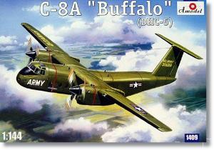
- De Havilland Canada C-8A Buffalo. USAF. 1970s.
- De Havilland Canada C-8A Buffalo. USAF. South Vietnam. 1970s.
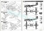
INSTRUCCIONES – INSTRUCTIONS:
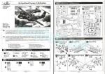
- Folleto en formato A4 de 4 páginas impresas en blanco y negro. Contiene un sumario histórico sobre el avión, una relación de pinturas esmaltes de Humbrol, un plano numerado de piezas, 9 secuencias de montaje y una página de perfiles.
- 4-page A4 brochure printed in black and white. It contains a historical summary about the aircraft, a list of Humbrol enamel paints, a numbered parts plan, 9 assembly stages and a page of profiles.
LO MEJOR – THE BEST:
- Carlinga e interior decentes. Opción de mostrar el interior.
- Decent cockpit and cargo bay. Ramp doors can be shown open.
LO PEOR – THE WORST:
- Piezas poco refinadas. Ajustes del fuselaje y las alas.
- Lack of refinement on some parts. Difficult assembly in fuselage and wings.
VALORACIÓN – CONCLUSION:
- Maqueta de serie limitada, única en plástico en cualquier escala por ahora. Detalles inusuales en otras marcas unidos a los habituales defectos en la factura de las piezas de este fabricante. Para modelistas con experiencia muy interesados en este avión.
- Short-run kit, the only one in plastic at any scale by now. It has unusual detail in other 1/144 kits coupled to moulding blemishes on some parts that is quite common in the manufacturer. Only for experienced modellers who are very keen to this aircraft.

La maqueta
El molde de Amodel en la escala menor 1/144 es el único de plástico que existe del DHC-5 por ahora, tanto en su versión militar norteamericana (C-8A) como en la canadiense (CC-115). Es un poco sorprendente que no haya maquetas de este material a escalas mayores, aunque tal vez no haya que culpar tanto al interés de los fabricantes como a la gran popularidad del muy parecido DHC-4 Caribou, mejor representado en todos los tamaños. Además de este C-8A, el fabricante sacó en su momento un CC-115 con dos versiones militares canadienses y un curioso modelo experimental XC-8A de fabricación conjunta canadiense-norteamericana. De esta forma, el modelista que esté interesado en hacer este avión se va a encontrar con las tres maquetas veinteañeras de Amodel por todo recurso.
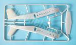
La maqueta tiene cinco bastidores, dos de ellos repetidos, un bastidor de piezas transparentes, una pequeña plancha de fotograbados, las calcas y las instrucciones. A primera vista la maqueta no parece tener el aspecto siniestro que cualquiera que conozca el paño de Amodel espera encontrar. La maqueta ofrece una carlinga más decente que la de la mayoría de maquetas actuales a esta escala y también la posibilidad de colocar la rampa de carga abierta. Las piezas transparentes, en especial las ventanillas, tienen un grosor más que aceptable a esta escala y muestran escasa o nula distorsión.
Para los aspectos menos buenos de esta edición hay que considerar que se trata de una maqueta de serie limitada y que por ello nos vamos a encontrar con algunas piezas muy poco refinadas y previsiblemente con malos ajustes, dado que muchas no están moldeadas con la finura necesaria en los bordes para que la unión sea uniforme y sencilla. Así pues, la masilla y la lija van a salir a escena cuando se trate de pegar, por ejemplo, las mitades del fuselaje y las de las góndolas de los motores. Hay además algunas rebabas por limpiar y afortunadamente ninguna marca de eyector que mencionar en el interior, lo que favorece a quienes pretendan mostrar el interior abierto. El plástico es más rígido que duro, en parte debido al grosor de algunos elementos de mayor tamaño, tales como el suelo y techo internos o las mitades del fuselaje.
Carlinga e interior
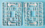
Los lados de la carlinga y el fuselaje no tienen ningún detalle ni tampoco marcas, como he dicho. La carlinga está formada por un panel trasero abierto en su centro, el suelo, dos asientos con reposacabezas poco realistas, el panel con los instrumentos marcados a diminuto tamaño, una consola entre los asientos y dos controles con los asideros separados. Todo esto ya es mucho más de lo que ofrecen otras marcas. Las calcas no traen los paneles, de modo que quien desee entretenerse algo más, puede pintarlos. La cubierta de la carlinga es una pieza un tanto gruesa con los paneles del techo y el parabrisas bien marcados según la escala.
La zona de carga dispone de un techo y un suelo separados. El suelo hace las veces de panza del fuselaje y probablemente aquí encontremos las primeras dificultades con el ajuste del fuselaje. El detalle interno de la zona de carga lo forman tres bancos por lado con asientos y respaldos separados y texturizados de manera un tanto ingenua y sin realismo. Este detalle es inusual en una maqueta de esta escala. Las patas de los asientos, 17 por lado y 34 en total, debe fabricarlas el modelista. Afortunadamente podemos guiarnos por las marcas del suelo para colocarlas. La parte de cola la cubren dos paneles sin detalle de distinta longitud que forman la compuerta de carga. El menor, que es la rampa de acceso, está moldeado con diminutas clavijas que teóricamente permiten colocarlo abierto junto con el de mayor tamaño, según se muestra en las instrucciones.
Las ventanillas laterales son piezas separadas sin rebajes en el lado interior del fuselaje, por lo que hay que insertarlas una por una cuidando que queden rasas con la superficie externa al ser piezas finas, como ya he mencionado. También vienen aparte las dos puertas de acceso laterales, que pueden colocarse abiertas, aunque las instrucciones no lo indican.
Fuselaje
Las mitades del fuselaje incluyen las superficies verticales de cola con el timón completo moldeado en el lado derecho. La parte superior tiene un rebaje para colocar las alas y hay huecos en la zona ventral para el suelo y las compuertas traseras, como he descrito arriba. También el morro de una pieza viene aparte. Hay otro morro alternativo con radar puntiagudo indicado para las otras versiones de este molde. Los bordes de las mitades son irregulares en ciertos tramos y necesitan ser refinados para lograr una unión sin fisuras.
Las escasas líneas de panel del fuselaje las veo bien de anchura, aunque, si se tiene el tiento necesario, convendría repasarlas en profundidad porque las que se han grabado en la parte superior son tenues, inconsistentes y desaparecerán con la primera capa de pintura por diluida que sea. Para no dejar nada al albur, y tratándose de Amodel, parece conveniente comprobar la anchura del techo y suelo internos antes de pegar el fuselaje.
En la zona ventral hay tres pequeñas piezas separadas simulando antenas u otros dispositivos.
Alas, motores y cola
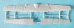
Las alas constan de tres piezas y tienen las superficies inferiores insertadas en la superior. Las puntas hay que modificarlas porque se han moldeado demasiado finas y con un extraño resalte en la costura interna de cada superficie inferior que debe eliminarse. Nada raro, pues ya dije arriba que masilla y lija serán compañeros inseparables en la construcción de esta maqueta. La pieza superior de las alas muestra el encastre del fuselaje en el centro y los de las góndolas están parcialmente reproducidos en los bordes de ataque y salida.
Los paneles están grabados con mejor aspecto que los del fuselaje y son consistentes, con mayor anchura en los que representan las superficies móviles. Las bisagras de los flaps y alerones son pequeñas aletas de fotograbado de forma distinta. Estos elementos están numerados e identificados correctamente en las instrucciones, pero su posición sobre el ala no está marcada. Las luces de aterrizaje son piezas transparentes insertadas en los bordes de ataque.
Cada góndola de motor viene reproducida en mitades con las superficies paneladas con finura. Las líneas necesitan el mismo repaso que en el fuselaje. Tanto el hueco de la toma bajo la hélice como el de salida posterior están bien abiertos. Hay dos tomas adicionales sobre y bajo el capó de cada motor, la superior sin detalle y la inferior al menos ahuecada. Las hélices tienen las palas separadas del buje con dos arandelas en la parte posterior del buje más el eje, que de poco va a servir ya que las hélices se introducen en los motores una vez pegadas las góndolas. Las palas son finas pero muestran una superficie rugosa y hay que refinarlas. Las góndolas van unidas a las alas tomando como referencia las pequeñas superficies encastradas en ellas.
Las superficies verticales de cola muestran un panelado decente y el timón bien marcado, aunque los filos delanteros y traseros son irregulares y tienen ligeras rebabas que deben refinarse antes de pegar las mitades del fuselaje. Los estabilizadores son de una pieza detallados con líneas de panel finas, aunque los timones no están marcados de forma diferente al resto. Esta pieza también necesita repasar con lija los bordes de salida.
Tren de aterrizaje
El pozo de la rueda delantera es una simple pieza plana pegada en el interior de las mitades del fuselaje sin marca para unir la pata. El soporte de las ruedas es fino y contiene el amortiguador de torsión y los ejes de las ruedas. Las ruedas son pasables y muestran los neumáticos definidos. La puerta anterior del pozo está detallada con un pequeño faro transparente.
Los pozos de las góndolas están huecos y vacíos. Hay cuatro pequeñas compuertas en cada pozo sin detalle interno. Los soportes están moldeados con el brazo de plegado separado y deben limpiarse de algunas rebabas situadas entre los finos huecos laterales de los brazos auxiliares. Los neumáticos tienen algunas rebabas y las superficies irregulares por refinar.
Calcas
La hoja está impresa por el mismo fabricante. Contiene insignias norteamericanas, el panel antirreflectante del morro, líneas y matrículas. Las calcas tienen un aspecto un tanto grueso y brillante. La mayoría muestra un ligero exceso de soporte. Los colores de las matrículas de cola y las de identificación del servicio (U.S. Army) de la primera opción de acabado están impresas, al menos en mi caso, en un color anaranjado rojizo en lugar del correcto amarillo que se aprecia en la ilustración de la caja.
Instrucciones
El folleto de instrucciones tiene un formato A4 y cuatro páginas impresas en blanco y negro que presentan un sumario histórico sobre el avión, una relación de pinturas esmaltes de Humbrol, un plano numerado de piezas, nueve vistas del montaje y una página de perfiles.
Aunque en general las vistas del montaje son claras, algunos elementos no están situados con precisión, como son los casos de las bisagras de las alas o la pata delantera. Necesariamente hay que recurrir a fotos del avión real para averiguar su posición correcta.
Las dos opciones de acabado incluyen dos aparatos pintados en Olive Drab de la década de 1970, uno de ellos situado en la Guerra de Vietnam, sin más diferencia entre ambos que algunas marcas del fuselaje y las alas, además de las matrículas.
Valoración
Resulta incauto minusvalorar esta maqueta por su tamaño creyendo que se armará en dos ratos, sin considerar que es un molde de serie limitada con las ventajas e inconvenientes que esto supone.
La maqueta ofrece un interior bastante decente en esta escala tanto en la carlinga como en la bodega de carga y la posibilidad de mostrar las puertas traseras abiertas con la condición de que se incluya al menos una parte del detalle interno que falta. También destaco las luces de aterrizaje y el faro del pozo delantero, pequeños elementos que mejorarán el aspecto final del modelo.
A cambio, el montaje no será sencillo principalmente debido a las piezas defectuosas e incluso infumables que Amodel y su control de calidad proporcionan. Es una pena porque el despiece pretende ser el de un producto a mayor escala y la maqueta me parece totalmente factible con paciencia y tiento pese a estos inconvenientes.
Puesto que las únicas alternativas son de resina en la misma escala y no hay ninguna otra de plástico por el momento, sólo la recomiendo a los que estén muy interesados en tener este avión en su vitrina y dotados con un suplemento de paciencia y tiento.◊

The kit
The Amodel 1/144 kits are the only ones in plastic of the DHC-5 by now, both in the American military version (C-8A) and in the Canadian version (CC-115). It is a bit surprising that there are no other kits of this aircraft in larger scales, but perhaps this is not so much due to the interest of the manufacturers as to the great popularity of the very similar DHC-4 Caribou, better represented in different scales. In addition to this C-8A, the manufacturer released a CC-115 with two Canadian military versions and a curious experimental XC-8A variant, a result of a Canadian-American joint project. Thus, the modeller who is interested in building this Buffalo will find the three twenty-year-old Amodel kits as everyting to resort to.
The kit comprises five sprues, one of them doubled, a clear sprue, a small fret of photo-etched parts, the decals and the instructions. At first glance, the kit does not appear to have the sinister appearance that anyone familiar with Amodel kits expects to find. The kit offers a more decent cockpit than most current kits in this scale and also the possibility of placing the load ramp open. The clear parts, especially the windows, have a more than acceptable thickness for this scale and show little or no distortion.
However, this is a full short-run release and therefore we are going to find unrefined parts and bad fitting on some spots, as many pieces lack finesse to get an easy join. Thus, putty and sandpaper will come into play when it comes to gluing, for example, the fuselage halves and the engine nacelles. There is also some flash to clean up and, fortunately no ejector marks on the interior, which favors those modellers who wish to show an open interior. Plastic is more rigid than hard, partly due to the thickness of some larger items such as the interior floor and roof or the fuselage halves.
Cockpit and interior
The cockpit sides have no detail or pin marks, as said. The cockpit contains a rear panel with an open access in the middle, a floor, two seats with unrealistic headrests, the instrument panel with tiny engraved gadgets, a console between the seats and two controls with separate horn grips. This is just much more than what other 1/144 kits offer today. There is no decal for the panel, so those who want to have a little more fun can paint it. The cockpit canopy is a bit thick piece with the roof and windshield panels neatly engraved according to scale.
The cargo bay has a separate roof and floor. The floor is also a part of the fuseage belly and will probably make the fitting of the fuselage halves a bit more difficult. Internal detail inside the bay consists of three benches per side with separate seats and backrests textured in a naive and unrealistic way. These texturised seats are quite unusual in a kit of this size. The seat legs, 17 per side and 34 in total, are provided by the modeller. Fortunately, we can use the marks on the floor as a guide to place them. The tail has two separate doors of different length. The smaller one, which is the load ramp, is moulded with tiny pins that should allow to pose it open, as shown in the instructions.
The side windows are separate pieces without recesses on the inner fuselage side, so they are attached one by one, taking care that they are flush with the external surface as they are thin pieces. The two side access doors also come separately and can also be placed open although the instructions do not show it.
Fuselage
The fuselage halves include the vertical tail surfaces with the complete rudder molded on the right side. The top side has a gap for the wings and there are more gaps in the belly for the floor and rear doors as described above. The one-piece nose is also supplied separately. An alternative nose with pointed radar is also included in the sprues. The edges of the halves are rough in places and need to be refined to achieve a smooth fit.
The few panel lines on the fuselage show a correct width but those on the roof need to be re-engraved with care because they are faint, inconsistent and will disappear with the first coat of paint. To leave nothing to chance, it also seems advisable to check the width of the inner roof and floor before gluing the fuselage sides.
In the ventral area there are three small pieces simulating antennas or other devices.
Wings, engines and tail
The wings consist of three pieces with the lower surfaces inserted into the upper one. The tips need to be modified because they are too thin and molded with a strange raised thick line just outboard of each lower surface. Nothing strange, as I said above that putty and sandpaper will be close mates during assembly. The upper wing piece shows the fuselage fairing in the middle and the engine nacelles fairings are also reproduced on the leading and trailing edges.
The panels have a better appearance than those on the fuselage and are consistent, with greater width on the control surfaces. The hinges of flaps and ailerons are small photo-etched fins of a different shape. These elements are numbered and identified correctly in the instructions, but their position on the wing is not clearly shown. The landing lights are provided as clear pieces inserted into the leading edges.
Each engine nacelle is reproduced in halves engraved with thin panel lines. The lines also need to be revised as on the fuselage. Both the intake opening under the propeller and the rear outlet are opened. There are two additional intakes above and below each cowling, the upper one is just a solid piece but the lower one is at least hollowed out. The propellers have the blades separated from the hub with two backplates behind it plus the shaft, which will be of little use since the propellers are inserted into the engines after the nacelles are glued. The blades are thin but show a rough surface that needs some sanding. The nacelles are attached to the wings using the faired leading and trailing edges as reference.
The vertical tail surfaces show decent panel lines and the rudder is engraved, although the leading and trailing edges are irregular and have slight flash that needs refinement before attaching the fuselage halves. The stabilizers are one piece detailed with very thin panel lines, although the lines on the rudders are not wider.
Undercarriage
The front wheel well is a simple flat piece glued to the inside of the fuselage halves with no holes to attach the leg. The leg is thin and contains the torsion arm and wheel axles. The wheels are decent and show defined tires. The forward door is detailed with a small clear taxi light.
The nacelle wells are hollow and empty. There are four small doors in each well with no internal detail. The legs are molded with the actuator separated and there is some flash present between the thin side gaps of the auxiliary folding arms. The tires have some flash and rough tires to be refined.
Decals
The sheet is printed by the manufacturer. It contains American markings, the anti-glare nose panel, lines and registers. The decals have a somewhat thick and shiny appearance. Most of them show a slight excess of carrier. The colors of the tail registers and the service identification (U.S. Army) of the first finish option are printed, at least in my sheet, in a reddish orange color instead of the correct yellow that can be seen in the boxart.
Instructions
The instruction brochure is A4 format and has four pages printed in black and white. It includes a historical summary of the aircraft, a list of Humbrol enamel paints, a numbered parts plan, nine assembly views and a page of profiles.
Although the assembly views are mostly clear, some pieces are vaguely located, such as the wing hinges or the front leg, so it seems indispensable to resort to photos of the real aircraft to find out their correct position.
The two finish options include two aircraft from the 1970s painted in overall Olive Drab, one of them from the Vietnam War with the only difference between them being some markings on the fuselage and wings, as well as the registers.
Conclusion
It is unwise to underestimate this kit because of its size as it is not just shake and bake. It is in fact a short-run kit with the advantages and disadvantages this implies.
The kit offers a fairly decent interior for this scale in the cockpit and cargo bay and the possibility of showing the rear doors open if the missing internal detail is provided by the modeller. I also want to highlight the landing lights and the front taxi light, small items that will improve the final appearance of the model.
In return, assembly will not be simple mainly due to the defective parts that Amodel and their quality control provide. It is a shame because parts are intended to be that of a bigger kit and the kit looks feasible despite these drawbacks.
Since the only alternatives are resin kits in the same scale and there are no other plastic ones at the moment, I only recommend it to those who are very interested in having this aircraft on their shelves and are equipped with a little extra patience and skill.◊
Publicado – Published: 1 / 2025
©www.jmodels.net

Debe estar conectado para enviar un comentario.