

Este artículo está dedicado a Jim Ellery, ex miembro de la Fuerza Aérea, allá en Tejas. Con la amargura del dolor.
This article is dedicated to Jim Ellery, a former member of the US Air Force, there in Texas. With the bitterness of pain.
De un vistazo – Quick look
MATERIAL Y PIEZAS
MEDIA & PARTS:
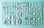
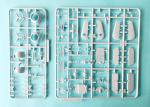
- Plástico inyectado (145 piezas), plástico transparente (24 piezas). Incluye 2 figuras.
- Injected plastic (145 parts), clear plastic (24 parts). Two figures included.
CALCAS – DECALS:
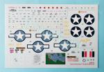
- Impresas por Cartograf. Insignias norteamericanas de dos tipos, panel de instrumentos, decoraciones del morro (noseart), numerales, códigos, marcas de cola y numerosos estarcidos. Aspecto muy fino y brillante. Saturación de color y registro correctos. Mínima película de soporte.
- Printed by Cartograf. Two types of US roundels, instrument panel, noseart, registrations and aircraft numbers, tail markings and plenty of stencils. Very thin and glossy finish. Correct saturation and register. No excess of carrier film.
OPCIONES – OPTIONS:
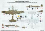
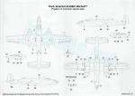
- North American B-25D-15 Mitchell. 41-30409 Lady Jane. 23rd Antisubmarine Squadron. Tampa (Florida, USA). July 1943.
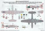
- North American B-25C Mitchell. Desert Warrior. 12th Bombardment Group (Medium). 81st Bombardment Squadron (Medium). Bolling Field (Washington DC, USA). July 1943. Aircraft crewed by Capt. R. Lower, Pilot Off. A. A. Martin (RCAF), Sgt. J. R. Dawdy, Sgt. J. B. Saragalo, Lt. F. R. Pond, Lt. T. R. Tate and Lt. W. O. Seaman.
INSTRUCCIONES – INSTRUCTIONS:
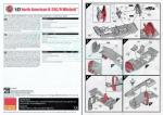
- Folleto A4 de 16 páginas impreso en color. Contiene un sumario histórico sobre el avión con especificaciones técnicas y 84 secuencias de montaje. Dos hojas separadas de formato A3 muestran perfiles a color de las alternativas de acabado con una lista de pinturas esmaltes de Humbrol y una guía para colocar los estarcidos de la maqueta, respectivamente. Hay un error concreto pero importante en el montaje (ver texto).
- 16-page A4 booklet printed in color. It contains a historical summary about the aircraft with technuical specifications and 84 assembly chapters. Two A3 separate sheets show profiles in color of two finishing choices with a list of Humbrol enamel paints and a guide to set the stencils, respectively. There is an important mistake in two assembly chapters (see text).
LO MEJOR – THE BEST:
- Buen detalle general. Múltiples opciones de construcción. Montaje asequible a modelistas menos expertos.
- Nice overall detail. Multiple assembly choices. Suitable assembly for less experienced modelers.
LO PEOR – THE WORST:
- Algunas marcas de la carlinga. Motores mejorables. Ausencia del compartimento de la radio. Leves errores y omisiones en las calcas.
- Some pin marks on the cockpit. Improvable engines. Lack of radio operator station. Slight mistakes and omissions on the decal sheet.
VALORACIÓN – CONCLUSION:
- Airfix atinó al lanzar los modelos iniciales del B-25, precisamente los que necesitaban una renovación. Buen detalle interno y externo, con algunos aspectos concretos más flojos y mejorables, unido a una gran variedad de alternativas de construcción. Asequible a modelistas con habilidades y experiencia media.
- Airfix hit the nail by releasing the early B-25 variants, precisely the ones that needed updating. The kit offers good internal and external detail, with a few weaker aspects that could be improved, along with a variety of construction choices. Suitable for modelers with average skills and experience.

La maqueta
Airfix renovó su viejo B-25 Mitchell en la escala 1/72 hace aproximadamente una década con esta maqueta de nuevo cuño y con la segunda, un B-25B (referencia A06020) que en el momento de escribir esta revisión parece estar a punto de reaparecer.
Dejando aparte maquetas muy antiguas, hoy tenemos básicamente tres moldes en esta escala. El más antiguo, de finales de los años 70, es el de Italeri, también copiado por AZ Model. A principios de este siglo salió la estupenda maqueta de Hasegawa, dedicada a las versiones B-25H y J, esta última reeditada con y sin morro transparente. De este molde hay copias de Revell y, más recientemente, de Eduard. Finalmente, está el molde de Airfix, dedicado a los modelos iniciales del Mitchell que a su vez cuenta con varias reediciones.
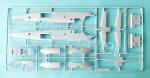
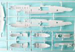
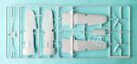
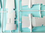
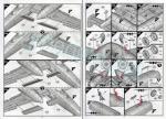
La caja trae siete bastidores de piezas, dos de ellos transparentes, la hoja de calcas y las instrucciones. Las piezas tienen un moldeado correcto y vienen limpias de rebabas y otras imperfecciones. Pese a que hay algunas marcas evidentes dentro del fuselaje y los pozos de las ruedas, el molde muestra una limpieza notable. El panelado negativo lo componen líneas de una finura y profundidad acorde a la escala, en mi opinión. Ignoro si falta o sobra alguna más porque no tengo planos fiables.
Las opciones de montaje permiten mostrar el tren de aterrizaje bajado o plegado, poner las escotillas de acceso bajo el fuselaje y las compuertas de la bodega de bombas abiertas o cerradas, pegar las superficies de control de la cola y los flaps de las alas en posición no neutra, elegir entre dos cubiertas transparentes de la carlinga según el modelo que deseemos construir, y, por último, la torreta ventral se puede colocar extendida o retraída.
Aunque difícilmente distinguible del B-25B exteriormente, el modelo C/D de Airfix muestra dos rasgos singulares de este último, como son la cúpula del navegante tras la cubierta de la carlinga y el paragolpes bajo el puro de cola, además de la doble ametralladora, fija y movible, en el puesto del morro. Estas características apuntan a que la maqueta representa un avión de producción final.
Revisión
Los lados internos de las mitades del fuselaje están detalladas solamente desde la bodega de bombas hasta el morro con el relieve de la estructura y algunos instrumentos representados en líneas finas. Hay marcas de eyector junto al morro acristalado y la cubierta de la carlinga de pilotaje que inevitablemente se deben tapar. Otras marcas están situadas en medio del detalle de la estructura y son más difíciles de disimular, aunque no serán advertidas cuando se cierre el fuselaje.
El suelo de la carlinga de pilotaje incluye el hueco de acceso del navegante, pilotos y bombardero así como el compartimento del navegante, con el asiento y la banqueta en posición desplegada además de algunos instrumentos en la pieza. La carlinga de los pilotos consta de dos asientos diferentes, el panel unido a los pedales y tres calcas para simular los instrumentos. Los controles vienen unidos en una pieza e incluyen la pequeña consola central en la base sin las palancas. Para cubrir la ausencia de arneses tenemos dos pilotillos patilargos que ya hemos visto en otras maquetas del fabricante.
Por delante de la carlinga hay que añadir el mamparo del compartimento del bombardero, bien detallado en su cara delantera, donde se incluye el respaldo del asiento. La parte posterior de la carlinga tiene otro mamparo aparte con un acceso abierto al puesto del navegante. Una vez añadidos ambos mamparos, se pega una pieza por debajo de la carlinga que simula tanto el suelo del compartimento del morro como el pasillo de acceso del bombardero. Por debajo de ella queda un espacio para incluir 25 gramos de lastre, que podrían ser pocos aun considerando que la parte posterior de la maqueta está casi vacía en su interior. La pieza tiene separados la base del asiento, el asiento en forma de sillín de bicicleta, algunos instrumentos en el lado derecho, la ametralladora fija moldeada con su afuste y la bolsa de casquillos vacíos, una pequeña pieza transparente en el borde delantero y la mira. La segunda ametralladora va insertada en la pieza transparente del morro.
La cubierta de la carlinga posee dos alternativas, ambas moldeadas con una sección del fuselaje por delante del parabrisas. Las piezas se diferencian en la estructura de soporte de los cristales. La elección de la pieza apropiada tiene como referencia la hoja de perfiles en color. El puesto de bombardero está cubierto por una pieza en el techo y el morro separado. Todas estas piezas transparentes tienen un buen detalle en la estructura y un grosor más que razonable, destacando la cubierta de la carlinga por su finura.
Antes de unir la carlinga al fuselaje hay que montar la bodega de bombas. El mamparo delantero contiene por el lado opuesto el panel trasero del compartimento del navegante y está unido a dos soportes laterales alargados para ayudar a pegar las alas. Una pieza similar cierra la bodega en el otro extremo. El techo de la bodega viene también separado con la escotilla del pasadizo para salvar el hueco. Si no deseamos mostrar la bodega, sólo hay que añadir, tras cerrar el fuselaje, una pieza que muestra las compuertas cerradas, Para colocar el compartimento abierto tenemos dos piezas laterales pegadas al fuselaje interno moldeadas con la estructura del hueco y las compuertas. Estos dos lados muestran un detalle bien conseguido y limpio. El interior incluye dos soportes laterales y cuatro bombas de 500 libras con las aletas exentas y un detalle pasable en las hélices de las espoletas.
El compartimento del operador de radio no está reproducido en la maqueta, pero en su lugar tenemos una pieza tras la bodega para instalar posteriormente la torreta dorsal y ventral. Hay un hueco en el centro con un soporte para introducir la columna de la torreta inferior. La cara superior muestra así mismo una muesca redonda donde apoyar la torre dorsal. Obviamente, esta pieza debe pegarse antes de cerrar el fuselaje.
Terminada esta operación, se puede cerrar el fuselaje haciendo pasar los dos largueros de soporte de las alas a través de cada mitad. Una sección de los paneles laterales del fuselaje por detrás de las alas están separados en dos piezas transparentes, pegadas desde afuera, que contienen dos ventanillas de iluminación y las dos redondas de escape a cada lado. También se añaden desde el exterior las diversas ventanillas repartidas a ambos lados del fuselaje, la cúpula del navegante y el acristalamiento de observación en la punta del puro de cola.
La torreta dorsal consta de cuatro piezas más la cúpula transparente. Las ametralladoras están unidas en una pieza con la mira y el afuste aparte. Por delante de ellas, otra pieza simula las cajas y las cintas de munición de cada arma. Estos elementos van pegados sobre la columna central, cuyo detalle se parece muy poco al real ni siquiera en el asiento que muestra la pieza.
La torre ventral está aún más simplificada. En este caso las ametralladoras se pegan a un afuste cilíndrico situado entre ellas que está unido a la columna central de la torreta. La punta inferior de la columna posee un pequeño cabezal ranurado que entra a presión en la base que hemos pegado antes dentro del fuselaje. Para mostrar la torreta plegada, no hay más que recortar la columna por encima del cabezal y pegarla sobre soporte inferior.
Las escotillas de acceso por debajo del fuselaje pueden colocarse abiertas o cerradas. El extremo de la cola lleva el paragolpes separado. Además, la parte superior está detallada con dos mástiles y una antena con carenado en forma de lágrima.
Las mitades de las alas coinciden en las puntas y van pegadas sobre los dos largueros laterales del fuselaje. Las mitades superiores están moldeadas con la parte de arriba de las góndolas de los motores, las tomas de aire de los bordes de ataque y sus correspondientes salidas posteriores, estas dos últimas bien perfiladas. Solamente las salidas del ala derecha llevan dos capotajes aparte. Igualmente bien definidas están las luces de las puntas. Los faros de aterrizaje son transparentes y constan de dos piezas: una primera interna con el faro y otra con la lente, añadida tras unir las semialas. Los flaps tienen piezas alternativas para colocarlos bajados o en posición neutra.
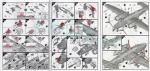
Para montar las góndolas de los motores debemos primero elegir si el tren de aterrizaje vamos a ponerlo bajado o no. En este último caso hay que pegar la compuerta del pozo cerrada, unir las mitades de cada góndola, y añadir la pieza frontal que soporta el motor y lleva unida la entrada de la toma superior. En el primer caso el procedimiento es similar, aunque antes hay que pegar la pata de la rueda comprobando que quede unida a la mitad externa de la góndola sin pegar esta pieza. Una vez que la pata está en su lugar, se monta la góndola sin la compuerta abierta. Esta pieza se añade junto con su actuador y el brazo de torsión de la pata casi al final del montaje. Las ruedas se proveen en mitades simulando peso. Muestran buen detalle en las llantas y los neumáticos tienen un dibujo de diamante demasiado sutil en la banda de rodadura.
El tren delantero consta de una pata insertada en la ranura del fuselaje y la compuerta, que podemos colocar cerrada si queremos mostrar el avión en vuelo.
Cada motor consta de dos coronas de cilindros. La interna está moldeada en una placa circular sobre la cual va pegada la externa. El detalle de los cilindros es pasable en la corona anterior y cabe mejorarlo. La caja de engranajes viene separada con el eje de la hélice en su interior. El capó es de una pieza con el anillo de aletas en posición cerrada aparte. Los pequeños carenados de las salidas sobre el capó vienen separados y huecos. Airfix ha incluido dos piezas de sobra para cubrir posibles pérdidas, Las hélices son de una pieza y tienen las palas finas, bien torsionadas y limpias.
Las superficies horizontales de cola forman un conjunto distribuido en dos mitades más los timones aparte provistos de ejes que permiten elevarlos o deprimirlos. Las instrucciones tienen un error de diseño en los capítulos 31 y 32, donde se aprecian los timones horizontales con los actuadores de las aletas del revés. Las piezas D32 y D33 deben colocarse invertidas de modo que estos actuadores queden en la cara superior de los timones, y no debajo de ellos. Este detalle también es válido para la maqueta del B-25B de Airfix. Las aletas y timones verticales poseen una distribución idéntica y están bien reproducidos con las luces de navegación nítidas. En este caso, los timones pueden ladearse pegándolos a las bisagras en un ángulo de 30º.
Como es costumbre en tiempos recientes, la hoja de calcas la imprime Cartograf. Contiene insignias norteamericanas de dos tipos, el panel de instrumentos, decoraciones del morro (noseart), numerales, códigos, marcas de cola y un buen puñado de estarcidos. Todas ellas muestran un aspecto muy fino y brillante con una saturación de color y registro correctos. La película de soporte es mínima.
Para el B-25C Desert Warrior Lifelike Decals ofrece una hoja que corrige las calcas de Airfix, básicamente los colores erróneos de las dos decoraciones del morro (mapa de las misiones realizadas y las condecoraciones conseguidas) más la ausencia del mote Earthquake pintado en amarillo por fuera de las góndolas de los motores.
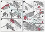
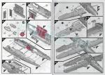
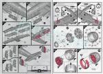
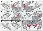
El folleto de instrucciones tiene un formato A4 y consta de 16 páginas en color. Contiene un sumario histórico sobre el avión con especificaciones técnicas y 84 secuencias de montaje claras en general, salvo por el error en los capítulos 31 y 32 y alguna omisión en la elección de la cubierta de la carlinga, como he mencionado. Dos hojas separadas de formato A3 muestran perfiles a color de las alternativas de acabado con una lista de pinturas de Humbrol y una guía para colocar los estarcidos de la maqueta respectivamente.
La primera opción de pintura nos presenta un B-25D destinado por la USAAF a misiones antisubmarinas en el Golfo de Méjico entre 1943 y 1944. Lleva un librea atractiva y bastante especial, compuesta del usual Olive Drab festoneado de verde oscuro en las superficies superiores y color blanco en las inferiores.
El B-25C Desert Warrior del Capitán Ralph Lower completó 52 misiones en el Norte de África y el Mediterráneo de julio de 1942 a septiembre de 1943. En el otoño de ese año (aunque Airfix lo sitúa en julio), el avión y su tripulación volvieron a los EE.UU., donde se les agasajó como héroes, para tomar parte en una campaña de adquisición de bonos de guerra. La librea de este aparato era menos elaborada, consistiendo sólo en color arena por arriba y un gris medio por abajo.
Valoración
Es indudable que Airfix atinó al escoger precisamente los modelos iniciales para darle nueva vida a su B-25, ya que su competidora Hasegawa está dedicada a las variantes finales H y J. La construcción de la maqueta me parece asequible para modelistas con habilidades y experiencia media e incluso algo menor. Dicho esto, parece necesario no desviarse demasiado de la secuencia de montaje que indican las instrucciones para no complicarlo innecesariamente.
Uno de los activos de esta maqueta son las variadas opciones de montaje, bastante ampliadas respecto a otras de igual porte. En general el detalle externo está bien conseguido y el interno resulta más que decente, salvo por la ausencia del compartimento de la radio y el flojo detalle en las torretas y los motores, que no son del todo malos, pero son claramente mejorables. Otro detalle menor, aunque perfeccionable, es el número de bombas dentro de la bodega, que podría haber llegado a las seis de 500 libras habituales.
Ya que este molde le va a durar a Airfix mucho tiempo, esperemos que se acuerden de hacer las necesarias correcciones, mínimas sin embargo, tanto en las instrucciones como en la hoja de calcas.◊


The kit
Airfix updated their old 1/72 B-25 Mitchell about a decade ago with this new-tool kit and a second one, a B-25B (reference A06020), which at the time of writing this review seems about to reappear.
Leaving aside very old offers, today we basically have three tools in this scale. The oldest one, from the late 1970s, is the Italeri kit, also copied by AZ Model. At the beginning of this century, Hasegawa released their excellent kit dedicated to the B-25H and J versions, the latter reissued with and without a clear nose. Revell and, more recently, Eduard also have copies of this kit. Finally, there is the Airfix tool, dedicated to the early Mitchell variants, which itself has had several reissues so far.
The box contains seven sprues of parts, two of them clear, the decal sheet, and the instructions. Parts are well-molded and free from flash and other blemishes. Although there are some obvious marks inside the fuselage and wheel wells, the molding is remarkably clean. Engraved panel lines are of a fineness and depth appropriate to the scale, in my opinion. I don’t know if any are missing or superfluous because I don’t have reliable plans.
Assembly options allow you to display the landing gear lowered or folded, pose the access hatches under the fuselage and the bomb bay doors open or closed, attach the tail control surfaces and wing flaps in non-neutral position, choose between two clear canopies depending on the variant you wish to build, and finally, the ventral turret can be displayed extended or retracted.
Although externally indistinguishable from the B-25B, Airfix C/D kit displays two unique features of the latter: the navigator’s astrodome behind the cockpit canopy and the tail bumper, in addition to the twin machine guns, one fixed and one flexible, in the nose position. These characteristics suggest that the kit represents a final production aircraft.
Review
The fuselage inner sides are only detailed from the bomb bay to the nose. They show the structural raised detail with thin lines and some instruments. There are marks next to the glazed nose and the cockpit canopy and these should be inevitably cleaned. Other marks are located in between the structural detail and are more difficult to fill, although they will not be evident once the fuselage is closed.
The cockpit floor includes the access opening for the navigator, pilots, and bombardier, as well as the navigator’s compartment, with the round seat in the unfolded position, along with some instruments on the piece. The pilots’ cockpit includes two different seats, the panel molded with the pedals, and three decals to simulate the instruments. The controls are one piece including the small center console at the base without the levers. To compensate for the lack of harnesses, there are two long-legged pilot figures, just the same we have already seen in other kits from the manufacturer.
In front of the cockpit, we need to attach the bomber compartment bulkhead, which is well-detailed on the front side and includes the seat back. The rear of the cockpit has another separate bulkhead with an open access to the navigator’s station. Once both bulkheads are added, a piece is glued underneath the cockpit representing both the floor of the nose compartment and the bomber’s access. Below this, there is room to include 25 grams of ballast, which might be insufficient even considering that the rear of the model is almost empty inside. The piece has separate parts for the seat base, a bike-like seat, some instruments on the right side, the fixed machine gun molded with its mount and empty casing pouch, a small clear piece on the edge, and the sight. The second machine gun is inserted into the clear glazed nose.
The cockpit canopy has two options, both molded with a fuselage section forward of the windshield. Parts slightly differ in the raised structure and number of windows. To choose the correct part for the variant you are building you need to check the profiles on the decal option sheet. The bombardier’s position is covered by a clear piece and a separate nose. All these clear parts have good structural detail and a reasonable thickness, with the cockpit canopy standing out for its thinness.
Before attaching the cockpit to the fuselage, you need to build the bomb bay. The forward bulkhead contains the rear panel of the navigator’s compartment on the opposite side and is attached to two side spars to help build the wings. A similar piece closes the bay at the other end. The bay roof is also separate, with the hatch of the passage to bridge the gap. If you don’t want to display the bay, you simply add a piece showing the doors shut after closing the fuselage. To display the open bay, there are two side pieces glued to inserts on the inner fuselage. These are molded with the structure of the sides and doors and look quite nice and clean. The interior includes two side racks and four 500 lb bombs with separate fins and passable detail on the fuze propellers.
The radio operator’s compartment is not included in the kit, but instead, there is a piece behind the bay for later mounting the dorsal and ventral turrets. There is a center mount for inserting the lower turret column. The upper surface also shows a round notch for the dorsal turret. Obviously, this piece is glued in place before closing the fuselage.
Once this is done, the fuselage can be closed by inserting the two wing spars through each half. A section of the fuselage side panels behind the wings is separated into two clear pieces glued from the outside and containing a window and a round emergency exit on each side. Also added from outside are the windows along both fuselage sides, the navigator’s astrodome, and the glazed fuselage tail tip.
The dorsal turret consists of four pieces plus the glazing. The machine guns come in a single piece, with separate sight and mount. In front of them, another piece simulates the ammo boxes and belts for each weapon. These elements are glued onto the centre column, but detail bears little resemblance to the real thing, not even in the seat shown on the piece.
The belly turret is even more simplified. In this case, the machine guns are glued to a cylindrical mount between them molded with the turret’s centre column. The lower end of the column has a small spring clip to be pressed into the base previously attached inside the fuselage. To display the turret retracted, you simply cut out the column above the clip and glue it onto the base.
The access hatches under the fuselage can be positioned open or closed. The tail bumper is provided as a separate part. The upper fuselage is detailed with two masts and a teardrop antenna.
The wing halves match at the tips and are glued onto the two side fuselage spars. The upper halves are molded with the top surfaces of the engine nacelles, the leading-edge air intakes, and their corresponding rear exhaust ducts. Only the right wing have two separate fairings for the exhaust ducts. The wingtip lights are well-defined. The landing lights consist of two clear pieces: an inner part molded with the light and an outer part with the lens, this one added after joining the wing halves. The flaps have alternative parts for attaching them in the lowered or neutral position.
To build the engine nacelles, we have to decide whether the landing gear will be lowered or not. In the latter case, the closed wheel well door is glued in place, the two halves of each nacelle joined, and the front engine mount piece added. This part is molded with the top air scoop front. In the former case, assembly is similar, although the wheel strut is first attached in place. Then, the nacelle is built without the door. This piece, along with the actuator and the strut torsion arm, is added in the last assembly steps. The wheels are provided in halves to simulate weight. They show good detail in the rims, and the tires have a diamond tread pattern that is too soft.
The nose landing gear consists of a leg inserted into a fuselage slot and a door, which can be attached closed if you want to display the aircraft in flight.
Each engine has two cylinder rows. The inner row is molded onto a round piece. Detail on the rows is just passable and could be improved. The gearbox comes separately with the propeller shaft inside. The cowling is a single piece with a ring of flaps separate and molded closed. The small exhaust stubs on the cowling are separate and hollow. Airfix have included two extra parts to cover any potential losses. The propellers are one piece and have thin, well-twisted, and clean blades.
The horizontal tail surfaces come in halves with separate elevators. These are provided with shafts that allow them to be raised or lowered. The instructions contain a design mistake in steps 31 and 32, where the elevators are shown with the fin tab actuators reversed. Parts D32 and D33 should be inverted so that these actuators appear on the rudders, not underneath them. This detail also applies to Airfix B-25B kit instructions. The fins and vertical rudders have an identical layout and are well reproduced with defined navigation lights. In this case, the rudders can be deflected by attaching them to the hinges at a 30° angle.
As usual, the decal sheet is printed by Cartograf. It contains two types of American roundels, the instrument panel, nose art, numbers, codes, tail markings, and plenty of stencils. All of them have a very fine and glossy appearance with correct color saturation and register. Carrier film is minimal.
For the B-25C Desert Warrior, Lifelike Decals offers a sheet that corrects the Airfix decals, primarily addressing the incorrect colors of the two nose markings (mission map and decorations earned) and the missing «Earthquake» nickname painted in yellow on the outside of the engine nacelles.
The instruction booklet is A4 and consists of 16 pages in color. It contains a historical summary of the aircraft with technical specifications and 84 clear assembly sequences, except for the mistake in chapters 31 and 32, as mentioned. Two separate A3 sheets show color profiles of the finishing / decal options, along with a list of Humbrol paints and a guide for setting the common stencils, respectively.
The first paint option shows a USAAF B-25D assigned to anti-submarine missions in the Gulf of Mexico between 1943 and 1944. It sports an attractive and rather unique livery, consisting of the usual Olive Drab trimmed with dark green on the upper surfaces and white on the lower surfaces.
Captain Ralph Lower’s B-25C Desert Warrior completed 52 missions in North Africa and the Mediterranean from July 1942 to September 1943. In the autumn of that year (although Airfix places it in July), the aircraft and its crew returned to the US, where they were welcomed as heroes, to take part in a war bond campaign. This aircraft’s livery was less striking, consisting only of a sand color on top and a medium gray underneath.
Conclusion
It’s undeniable that Airfix hit the nail in choosing the early models to breathe new life into their aging B-25, as their competitor Hasegawa is focused on the later H and J variants. The kit’s construction seems quite suitable for modelers with average experience and skill. That said, it seems necessary to follow the assembly sequence indicated in the instructions quite close to avoid unnecessary difficulties.
One of the strengths of this kit is the variety of assembly options, more extensive than those offered in other Airfix releases. In general, external detail looks accurate, and it is more than decent inside the fuselage, except for the absence of the radio compartment and the weak detail on the turrets and engines, which aren’t too bad, but are clearly improvable. Another minor drawback, though also improvable, is the number of bombs inside the bay, which could have been the usual six 500lb bombs.
Since this tooling is going to last Airfix a long time, let’s hope they remember to make the necessary corrections, however minor, both in the instructions and the decal sheet.◊
Publicado – Published: 2 / 2026
©www.jmodels.net

Debe estar conectado para enviar un comentario.