
De un vistazo – Quick look
MATERIAL Y PIEZAS
MEDIA & PARTS:
- Plástico inyectado (61 piezas), plástico transparente (12 piezas), resina (13 piezas).
- Injected plastic (61 parts), clear plastic (12 parts), resin (13 parts).
CALCAS – DECALS:
- Insignias norteamericanas de dos tipos, insignias de unidad, paneles antirreflectantes, líneas del fuselaje, alas y cola, marcas de cola, matrículas y rótulos identificativos. Aspecto fino y brillante con buena saturación de color y registro. Sin excesivo soporte.
- Two types of US Navy cockades, unit badges, anti-glare panels, fuselage, wing and tail stripes, rudder stripes and registers. Thin and glossy finish with good color saturation and in register. No excess of carrier.
OPCIONES – OPTIONS:
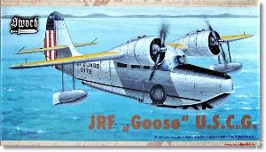
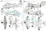
- Grumman JRF-3 Goose. U.S. Coast Guard. V176. Port Angeles (Washigton State, USA), 1943.
- Grumman JRF-55 (JRF-5G?) Goose. U.S. Coast Guard. 4792. USCGS San Francisco, 1951-52.
INSTRUCCIONES – INSTRUCTIONS:
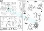
- Folleto de formato A5 con 12 páginas impresas en blanco y negro. Contiene una introducción histórica sobre el avión con datos técnicos, un plano numerado de piezas, 14 secuencias de montaje y 2 páginas de perfiles. Las referencias de color son genéricas.
- 12-page A5 format booklet printed in black and white. It contains a historical summary on the aircraft with technical data, a numbered parts plan, 14 construction steps and 2 pages of profiles. Color references are generic.
LO MEJOR – THE BEST:
- Avión inusual. Piezas de resina. Detalle interno decente aunque no muy completo.
- Unusual aircraft. Resin parts. Decent interior despite not being fully detailed.
LO PEOR – THE WORST:
- Ruedas, timón vertical y cubierta transparente moldeados en mitades.
- Wheels, rudder and canopy moulded in halves.
VALORACIÓN – CONCLUSION:
- Se reeditan muy poco tanto el avión como este molde en particular. Aunque es una maqueta de serie limitada, no es de las que deba plantear serios retos al modelista de cierta experiencia. Tiene margen de mejora interno y externo pero el buen detalle de las piezas de resina la hace muy factible simplemente de caja.
- This is a very unusual aircraft and the kit is rarely reissued. Despite being a short run, it should not pose any special difficulties to the modeller with some experience. It has room for internal and external improvement but the resin parts included also allow a nice build from the box.

La maqueta
El Grumman G-21 había sido un raro en el modelismo hasta que a inicios de este siglo algunas marcas checas lanzaron varias maquetas en la escala 1/72 y 1/48 todas ellas de serie limitada, por lo que no se reeditan muy asiduamente. Este molde de Sword también es de la primera década del siglo. Sword editó tres cajas con diferentes modelos, generalmente en versiones militares. También AZ Models hizo dos reediciones a partir de este molde posteriormente.
De la primera a la segunda caja de Sword, que es sobre la que escribo en este artículo, no sólo cambiaron las calcas, sino también la carlinga y las burbujas laterales de observación que llevaban algunas versiones, que pasaron de ser piezas vacuformadas a plástico transparente. La caja de esta edición resulta curiosa porque los lados están fastuosamente pintados como si de un cofre de madera con asas y bisagras metálicas se tratase. La farfolla termina pronto; el tiempo que se tarda en comprobar que no hay tesoro ni joya dentro, sino una simple maqueta de plástico.
La maqueta tiene dos bastidores de piezas grises, dos bastidores de piezas de plástico transparente, algo más de una decena de piezas de resina en distintos bebederos, las calcas y las instrucciones. La apariencia del molde recuerda a otros de hace un par de décadas de compañías afines como Special Hobby y MPM. Hay ligeras rebabas en los bordes de algunas piezas de mayor tamaño como las alas, estabilizadores y timón vertical. El fondo de cada pozo posee marcas dificultosas de limpiar por su posición. Las demás marcas de eyector positivas no afectan al detalle ni son imprescindibles de limpiar, aunque acaso convenga hacerlo en el interior del fuselaje y las alas, las primeras por estética y estas últimas porque podrían impedir pegarlas correctamente.
El grabado de los paneles y otros detalles es fino y preciso, pero tiene escasa nitidez en el fuselaje y es algo mejor en las alas. No creo que esto tenga mucha importancia cuando llegue el turno de pintar.
La única opción de montaje consiste en cortar y reemplazar el extremo del escalón ventral del fuselaje por una pieza de resina que describiré más abajo.
Calinga y cabina
Los lados internos de la carlinga y la cabina no tienen detalle. Como he dicho, solamente hay una marca a cada lado de la cabina de pasaje que no es imprescindible limpiar del todo. La carlinga está formada por un suelo, común a los dos espacios, un panel delantero, un excelente panel con los instrumentos en relieve, dos controles de resina unidos al panel, los asientos de resina con los cinturones moldeados sobre ellos y bases separadas, además de un mamparo trasero grabado en negativo por una cara, con la puerta de acceso a la carlinga y una ventanilla grabada sin pieza transparente. Los asientos y el panel son lo mejor de todo.
La cabina de pasaje consta de cuatro asientos de resina y un mamparo trasero con un acceso grabado en la cara anterior únicamente. Hay un mamparo vertical adicional tras este al que va pegado otro horizontal que hace las veces de fondo del pozo de la rueda de cola. Según indican las instrucciones, parece conveniente añadir la rueda de cola antes de pegar el fuselaje puesto que parece más difícil hacerlo en una etapa posterior.
Antes de pegar las mitades del fuselaje se añaden las ventanillas, todas ellas separadas y finas, más los pozos de las ruedas, para cuyo ajuste hay que recortar una pequeña cuña en el hueco del fuselaje.
Fuselaje
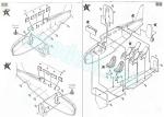
Las mitades están moldeadas con la deriva, pero sin el timón vertical. Como ya he dicho, los paneles están bien grabados en todas las superficies, aunque sin mucha nitidez. Las puertas laterales están bien marcadas, lo mismo que la escotilla superior del morro. Por delante de esta hay una pequeña bita de amarre.
Una pieza en forma de U simula un perfil colocado por delante de la quilla para evitar salpicaduras. Aunque el avión dibujado en la caja lo lleva, lo cierto es que este dispositivo sólo se ve en fotos de aparatos civiles y también lo lleva un Goose conservado en un museo. Ni el Goose V176 ni tampoco el 4792 lo tenían instalado, como demuestran las fotos de Internet. Tampoco lo he visto en ningún otro aparato estadounidense de uso militar.
El parabrisas vacuformado de la primera edición se ha sustituido por otro de plástico transparente que incluye parte del techo de la carlinga. Desgraciadamente, está separado en mitades, lo que complica un poco el montaje de la pieza. Ambas mitades son finas y están bien detalladas con las ventanillas laterales que se abrían deslizándolas hacia detrás. Sobre el techo hay que colocar el mástil de la antena.
Sobre la parte superior del fuselaje, moldeado en la cara superior de las alas, hay que añadir la antena carenada del radar y dos soportes de antenas. Los soportes y este tipo de antena son más adecuados para un Goose de posguerra, ya que los del periodo de la guerra mundial carecían de estos soportes y su antena era de anillo.
El escalón de la quilla tiene una pieza alternativa de resina provista de huecos en su frontal y lados. Para colocarla hay que recortar el borde del escalón marcado con líneas grabadas. Aunque los perfiles de las instrucciones y la propia ilustración de caja tienen el hueco lateral del escalón, las fotos del V176 no lo muestran. Este detalle sí aparece en otros aviones datados en tornos a 1943 (por las marcas nacionales con borde rojo) y de posguerra.
Alas, motores y cola
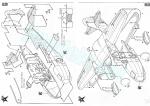
Las alas están separadas en tres superficies. En este caso la mitad superior incluye en su centro una sección del fuselaje y las mitades inferiores están separadas. Las piezas contienen las mitades de las góndolas de los motores moldeadas sin las cubiertas de los motores. El detalle de las superficies está bien definido, tanto el grabado de los paneles como las bisagras y actuadores de los alerones y flaps. Las rejillas de ventilación de los motores aparecen marcadas aunque están muy poco ahuecadas. El tubo Pitot es una pieza aparte.
Los flotadores está separados en mitades con los soportes unidos a uno de los lados. Las marcas para pegarlos en las alas están horadadas.
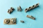
Las cubiertas de los motores están seccionados en mitades con los motores pegados en su interior. Están detalladas con los escapes en la parte superior separados en dos piezas. Cada góndola tiene una toma lateral de resina con su extremo ahuecado. También los motores son de resina y de ellos sólo tenemos la corona externa, que muestran un detalle muy notable. Las hélices tienen el buje separado, las palas son finas y están bien perfiladas. Una vez montados, los motores se pegan a cada góndola sobre una pieza circular que tapa el hueco que forman las mitades del fuselaje.
Los estabilizadores son de una pieza moldeada con dos pequeños vástagos para unirlos al fuselaje, aunque son demasiado cortos y casi inservibles. Los paneles de cada estabilizador están bien trazados y tanto la aleta como las bisagras son nítidos. Los timones tienen los contrapesos separados.
El timón vertical está separado en mitades. Esto hace que la pieza tenga una apariencia muy gruesa que no impide que los paneles, aleta y bisagras están bien representados.
Tren de aterrizaje
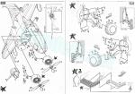
El montaje del tren principal no parece tan sencillo como aparenta. Cada lado cuenta con una pata detallada con una pequeña varilla en la parte superior, dos actuadores en forma de V y N respectivamente, la tapa del pozo y la rueda. Los actuadores están unidos al fondo del pozo y la pata. Afortunadamente, las instrucciones indican con claridad su posición con vistas frontales de cada lado. Las ruedas están divididas en mitades. El detalle externo es decente y el interno no demasiado bueno y carecen del hueco para introducir el eje. Las patas tampoco tienen eje.
La rueda de cola está hecha en una sola pieza con buena definición, pero hay ligeras líneas de molde en el neumático y el brazo de torsión al no ser hueco posee un aspecto un poco tosco.
Calcas
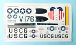
La hoja tiene buen porte y muestra insignias norteamericanas de dos tipos, insignias de unidad, los paneles antirreflectantes del morro, líneas del fuselaje, alas y cola, marcas de cola, matrículas y rótulos identificativos. Las calcas muestran aspecto fino y brillante con buena saturación de color y un buen registro. No contienen excesivo soporte.
Instrucciones
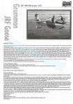
El folleto de instrucciones tiene un formato A5 y consta de 12 páginas impresas en blanco y negro. Contiene una introducción histórica sobre el avión con datos técnicos, un plano numerado de piezas, 14 secuencias de montaje con algunas vistas de detalle y dos páginas de perfiles. Las referencias de color son genéricas.
La primera terminación muestra un aparato bastante conocido (V176) que era en realidad un JRF-2 y no -3 (poco importa porque ambos modelos eran casi iguales) de los Guardacostas norteamericanos con base en el estado de Washington y accidentado en abril de 1943. La base y su final no lo indican las instrucciones, pero he hecho averiguaciones por mi cuenta.
La segunda versión es también un aparato de los Guardacostas cuyo modelo está identificado como JRF-55, que debe ser un error por JRF-5G, ya que fue este el modelo transferido por la US Navy al servicio de Guardacostas. Este aparato lleva escarapelas nacionales con barras laterales empleadas desde 1947. Hay imágenes de este aparato en Internet e información que asegura que tenía su base en San Francisco entre 1951 y 1952.
Valoración
Es una pena que las grandes marcas no le presten atención a este avión con tantas versiones civiles y militares, más sus posibilidades de acabado al haberse empleado en un buen número de países. Ciertamente también se reedita con muy poca frecuencia este molde de Sword y resulta cada vez más difícil de encontrar incluso con el marbete de AZ Models.
Aunque se trata de una maqueta de serie limitada, no es de las que deba plantear serios retos al modelista con cierta experiencia. Tiene margen de mejora interno y externo pero el buen detalle de las piezas de resina la hace muy factible simplemente de caja.◊

The kit
The Grumman G-21 had been an almost neglected topic in modelling until the beginning of this century, when some Czech brands launched several 1/72 and 1/48 short-run kits. As time passes they are rare to find as are not reissued very often. The Sword kits also date back from the first decade of the century. The manufacturer released three boxings with different variants, mostly in military liveries. AZ Models reissued two kits from this same tool a few years later.
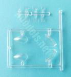
From the first to the second Sword boxing, which is the kit I am writing about in this article, there was a change of decals and also in the vac-formed canopy and observation blisters that some versions sported, which here are provided as injected clear pieces. The box in this release is peculiar because the sides are lavishly painted as if it was a wooden chest with metal handles and hinges. The mirage ends soon: the time one checks there is no treasure or jewel inside, but just a plastic kit.
The kit has two sprues of grey parts, two clear sprues, resin parts cast in different blocks, the decals and the instructions. The first impression of the kit’s parts reminds of other releases from a couple of decades ago produced by kindred companies such as Special Hobby and MPM. There are slight flash on the edges of the wings, stabilizers and vertical rudder. The bottom of each well has marks that are difficult to clean up due to their spot. The other positive ejector marks do not affect detail nor are essential to clean, but it may be advisable to do so inside the fuselage and wings; the former to improve appearance and the latter because the marks could interfere with attachment.
The engraving of panels and other detail are fine, but it is not very sharp on the fuselage and is a bit better on the wings. I do not think this will be very important when it comes the time to paint. The only assembly choice is to cut the ventral fuselage step and replace it with a resin part which I will describe below.
Cockpit and cabin
The cockpit and cabin sides are not detailed. As said, there is only one mark on each side of the passenger cabin which is not essential to clean up. The cockpit consists of a floor, shared with the cabin, a forward bulkhead, an excellent instrument panel with raised gadgets, two resin control wheels attached to the panel, two resin seats with the belts moulded on and separate bases, plus a rear bulkhead engraved with the door and a window only on one side. The window is engraved and has no gap or clear piece. The seats and the instrument panel are especially outstanding.
The passenger cabin consists of four resin seats and a rear bulkhead with an access engraved on the front side only. There is an additional vertical bulkhead behind this with a horizontal piece to render the bottom of the rear well. According to the instructions, the tailwheel is attached before gluing the fuselage as it seems more difficult to do this at a later assembly stage. Before joining the fuselage halves, you add the windows, all of them provided as thin separate clear pieces, plus the wheel wells. To install these you need to trim a small wedge in the fuselage gap.
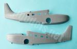
Fuselage
The fuselage halves are moulded with the fin, but without the vertical rudder. As said, the panels are well engraved on all surfaces, although not very sharply. The side doors and the nose upper hatch are correctly defined. Ahead of the hatch there is a small H-bitt.
A U-shaped piece renders the anti-spray skirts on the forward chine. Although the Goose depicted on the artbox have them, in fact the skirts are only seen in photos of civilian aircraft and they are also fitted to a Goose preserved in a museum. Neither the Goose V176 nor the 4792 had them installed as Internet pics show, I have not seen them on any other US military Goose either.
The vac-formed windscreen of the first boxing is now a clear plastic replacement including the cockpit roof. Unfortunately, the piece is moulded in halves, which makes assembly a little more delicate. Both halves are thin and well detailed with side sliding windows. The cockpit roof is provided with an antenna mast.
The cabin roof, moulded on the upper wing piece, has a teardrop radar antenna and two further masts. The masts and this type of antenna are suitable for a post-war Goose, as the WWII Goose lacked the masts and had a loop antenna.
The hull step has an alternative resin piece with front and side openings. Obviously, you need to cut out the hull step following the line engraved on the fuselage pieces. Again, the artbox and the profiles in the instructions depict the side openings of this piece, but pics of the V176 do not show it. This detail does appear in other pics of Gooses dated around 1943, as they wear national markings outlined in red, and from the post-war period.
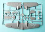
Wings, engines and tail
The wings are separated into three pieces. The upper half includes a fuselage section in the middle while the lower halves are separated. Parts contain the halves of the nacelles moulded without the cowlings. Surface detail is nice on the panels, hinges and actuators of ailerons and flaps. The engine gills are engraved although they look a bit shallow. The Pitot tube is a separate piece.
The floats are separated into halves with the struts moulded on one side. The holes for gluing them on the wings are drilled on the pieces.
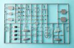
The engine cowlings are also provided in halves with the engines glued inside. They are detailed with the exhausts separated in two lengths. Each nacelle has a side resin intake with the front hollowed out. The engines are also resin pieces with only the outer row of cilinders moulded on a flat round base. The rows show a very nice sharp detail. The propellers have separate hubs with thin and well profiled blades. Once assembled, the engines are glued onto round pieces covering the nacelle gaps.
The stabilizers are one-piece provided with two small pins for fuselage attachment, but these are too short and almost useless. The panels are well engraved and both the fin and the hinges are clearly defined. The rudders have separate mass balances.
The vertical rudder is separated in halves. This makes the piece look very thick but the panels, fin and hinges are well represented.
Undercarriage
The main gear assembly does not seem as straightforward as it looks. Each side features a detailed leg with a small rod on top, two V-shaped and N-shaped actuators, the well door and the wheel. The actuators are attached to the bottom of the well and the leg. Fortunately, the instructions indicate where to attach them with front views of each side. The wheels are split into halves. The outer hubs are fine but the internal ones are not so good and lack a hole for the axle. The legs also have no axle moulded on them.
The tail wheel is attached to the leg and has good definition, but there are small seam lines on the tire and the solid torque links have a chunky look.
Decals
The sheet includes two types of US Navy cockades, unit badges, anti-glare panels, fuselage, wing and tail stripes, rudder stripes and registers. The decals have a thin and glossy finish with good color saturation and are in register. There is no excess of carrier.
Instructions
The instruction booklet is A5 format and consists of 12 pages printed in black and white. It contains a historical introduction to the aircraft with technical data, a numbered parts plan, 14 assembly chapters and two pages of profiles. Colour references are generic.
The first paint finish shows a fairly well-known aircraft (V176) which was actually a JRF-2 and not a -3 (it doesn’t matter because both variants were almost identical) of the US Coast Guard based in Washington and crashed in April 1943. The base and its fate are not indicated in the instructions, but I have made my own inquiries.
The second version is also a Coast Guard aircraft identified as a JRF-55, which must be a mistake for JRF-5G, since this was the variant transferred by the US Navy to the Coast Guard service. This aircraft carries national cockades with side bars used since 1947. There are images of this aircraft on the Internet and information stating that it was based in San Francisco between 1951 and 1952.
Conclusion
It is a shame that the big brands do not pay attention to this aircraft that had so many civil and military variants, plus a lot of finishing possibilities as it was used in many countries. Unfortunately, this kit has not been reissued for many years and is becoming difficult to find even with the AZ Model label.
Although this is a limited-run kit, it should pose no challenges to the modeller with some experience. It has room for internal and external improvement but the quality resin parts included can turn it into a nice model just from the box.◊
Publicado – Published: 1 / 2025
©www.jmodels.net

Debe estar conectado para enviar un comentario.