
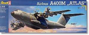
De un vistazo – Quick look
MATERIAL Y PIEZAS
MEDIA & PARTS:
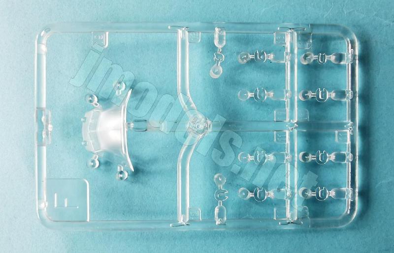
- Plástico inyectado (143 piezas), plástico transparente (11 piezas).
- Injected plastic (143 parts), clear plastic (11 parts).
CALCAS – DECALS:
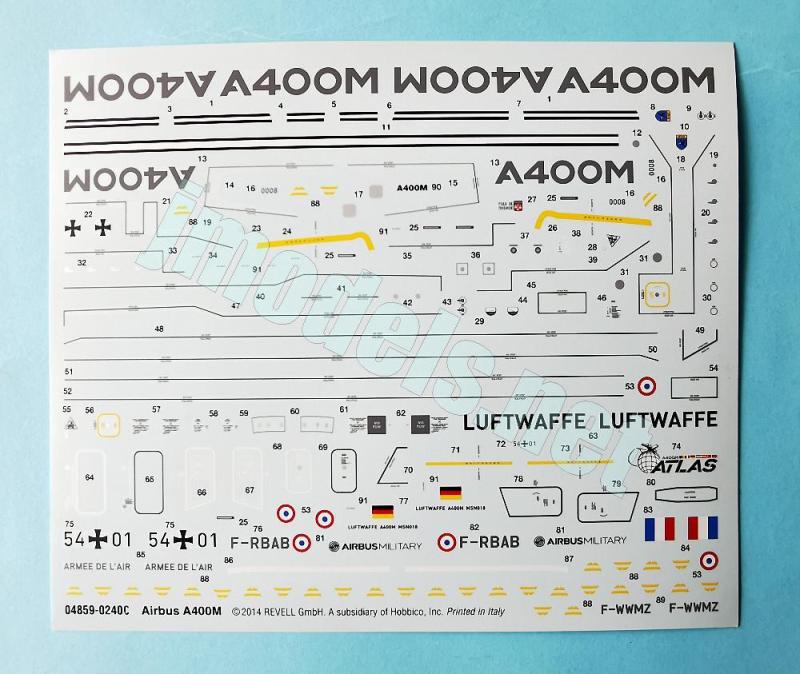
- Insignias nacionales, logotipos, códigos y matrículas, líneas del fuselaje y las alas, numerosos estarcidos. Finas con aspecto brillante. Buena nitidez y registro. Sin exceso de soporte.
- National markings, logos, codes and registrations, wing and fuselage lines, plenty of stencils. Thin and glossy finish. Good sharpness and register. No surplus carrier.
OPCIONES – OPTIONS:
- Airbus A400M “Atlas”. c/n 0006. F-WWMZ. 2013.
- Airbus A400M “Atlas”. c/n 0018. 54+01. German Air Force. Luft Transport Geschwader 62. Wunstorf (Germany), 2014.
- Airbus A400M “Atlas”. c/n 0008. F-RBAB. “Ville de Toulouse”. French Air Force. 2014.
INSTRUCCIONES – INSTRUCTIONS:
- Folleto A4 de 12 páginas impreso en blanco y negro. Contiene una introducción histórica con datos técnicos, una lista de colores con equivalencias de pinturas del fabricante, 47 capítulos de montaje y 2 páginas y media de perfiles.
- 12-page A4 brochure printed in black and white. It contains a historical introduction with technical data, a list of colors with Revell paint matches, 47 construction chapters and 2 pages and a half of profiles.
LO MEJOR – THE BEST:
- Carlinga decente. Bodega de carga detallada. Opciones de montaje.
- Decent cockpit. Detailed cargo bay. Assembly choices.
LO PEOR – THE WORST:
- Fuselaje en cuatro piezas. Luces de aterrizaje no transparentes.
- Fuselage provided in four pieces. Landing lights not provided as clear parts.
VALORACIÓN – CONCLUSION:
- Tiene un detalle notable para su escala, aún con la falta de algunos elementos mínimos y un montaje innecesario en el doble fuselaje. Las opciones de construcción están bien elegidas y ofrece posibilidades de crear una escena a su alrededor. Para amantes de los cargueros del peso pesado con espacio en la vitrina.
- This kit has a remarkable detail for the scale, despite the absence of a few minor elements and an unnecessary assembly in the double fuselage. Construction alternatives are well-chosen and offer possibilities for creating a scene around it. Ideal for heavy haulers enthusiasts with plenty of room in their cabinets.

La maqueta
Antes de esta maqueta Revell sacó el A400M en la escala 1/72. Una vez vi a un tipo salir de una tienda con la maqueta de esa escala en las manos y tenía serios problemas para sujetar la caja debido a su tamaño. Eso pasa por no llevar antes un carrillo de mano sobre ser agonías, claro. La maqueta que me ocupa hoy tiene una longitud de 32 cm por 29,3 cm de envergadura, según el fabricante. Con ese porte, ya cabe imaginar el de su hermana mayor. En cualquiera de los dos casos, hay que hacer bastante sitio donde vayamos a posarlas.
Hasta ahora, esta caja solamente ha tenido una reedición en 2024 (ref. 03789) y venía además acompañada de un Panavia Tornado como escolta, a diferencia del A400 en la escala 1/72 que lleva varias copias con menos intervalo entre ellas.
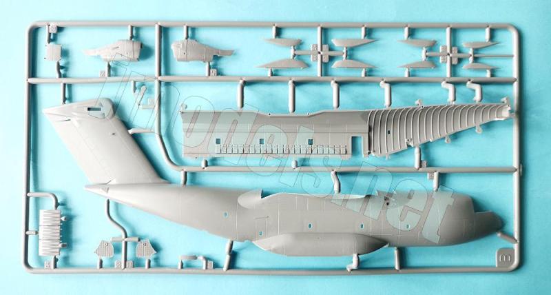
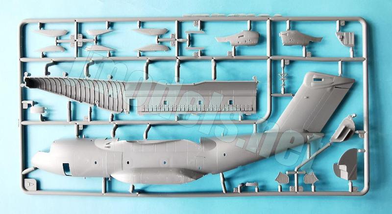
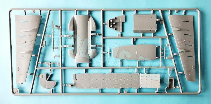
La caja nos entrega seis bastidores de piezas grises, un bastidor transparente, la hoja de calcas y las instrucciones. Las piezas están bien moldeadas y en general presentan buena nitidez en los detalles, con algunos cilindros del eyector. El panelado es en su mayoría grabado, pero también hay algunas pocas líneas en relieve representadas con acierto. El grabado de los paneles es tan fino y preciso que será difícil dejarlo evidente tras pintar sobre algunas zonas, como las alas por ejemplo. Más aún con un color tan oscuro como el de la librea habitual del A400M. Hay gran multitud de marcas de eyector negativas por todas partes. Aparentemente casi todas deben estar en zonas no visibles. En caso contrario, lo indico en su lugar correspondiente.
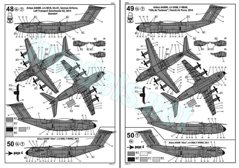
El montaje permite presentar el modelo de tres formas: en vuelo o en tierra con las puertas de acceso y carga abiertas o cerradas. Las terminaciones de pintura son idénticas, diferenciándose en las calcas, que permiten reproducir dos aviones militares (Luftwaffe y Armée de l’air) y el primer aparato de prueba construido con las especificaciones definitivas y finales de serie por parte de Airbus.
Reseña
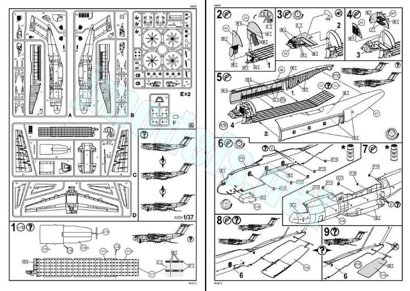
En la página 5 de las instrucciones encontramos las tres alternativas de montaje de la maqueta con un primer capítulo que nos indica el corte que debemos hacer en las piezas del suelo de la bodega y del extremo inferior del fuselaje para colocar la rampa de carga abierta.
Las mitades del fuselaje vienen separadas en cuatro piezas, lo que aparenta complicar el montaje. Dos de ellas reproducen el exterior y otras dos el interior, excepto la cabina y el suelo del compartimento de carga separados. La carlinga dispone de un suelo con el panel de instrumentos, detallado con calca, la consola central y dos laterales, más los asientos para tres tripulantes. Tras la carlinga hay hasta cuatro mamparos dispuestos transversalmente en paralelo detallados con accesos, paneles y dos literas. El asiento del operador de carga viene en la parte anterior de la pieza del suelo de la bodega y las escaleras de acceso a la cubierta de vuelo en uno de los mamparos.
Los lados internos del fuselaje están reproducidos con finura y contienen los asientos de tropa más un costillaje muy bien definido en relieve en la zona trasera. El suelo de la bodega está detallado con multitud de puntos de anclaje para la carga, nítidos pese a su diminuto tamaño. Si elegimos dejar la rampa de carga bajada, el extremo trasero separado lleva un par de brazos hidráulicos, una ampliación de la rampa y dos patas extensibles de apoyo en el suelo. De la grúa de carga no hay rastro.
Las mitades interiores del fuselaje se pueden pegar una vez terminada la carlinga y la rampa en la configuración elegida. En su lado externo estas piezas muestran multitud de marcas de eyector y los huecos de las ventanillas con un resalte en los contornos que debe encajar en los huecos del fuselaje externo. Algunas marcas están próximas a las ventanillas sin llegar a afectarlas.
Antes de pegar este ensamblaje interno a los lados externos del fuselaje se le añaden el pozo delantero, un contrapeso de 40 gr dentro del morro, y las ventanillas. Si el ajuste es bueno (no lo he comprobado), los marcos de las ventanillas deberían coincidir y la carlinga encajar sin dificultad en las muescas laterales del fuselaje.
Las mitades exteriores del fuselaje integran algunas aletas y dispositivos electrónicos en la parte superior e inferior, más otros en piezas aparte. La cubierta de la carlinga posee un grosor bastante razonable y las ventanillas se ven bien representadas. La sonda de repostaje viene separada. La puerta lateral de acceso se puede colocar abierta y lleva la escalera integrada en la pieza. Las puertas laterales situadas por detrás de las alas, dispuestas para el lanzamiento de paracaidistas, aparecen cerradas, aunque el hueco interno sí está representado. La parte externa se puede detallar opcionalmente con el deflector de aire situado por delante de la puerta, un detalle bien visto.
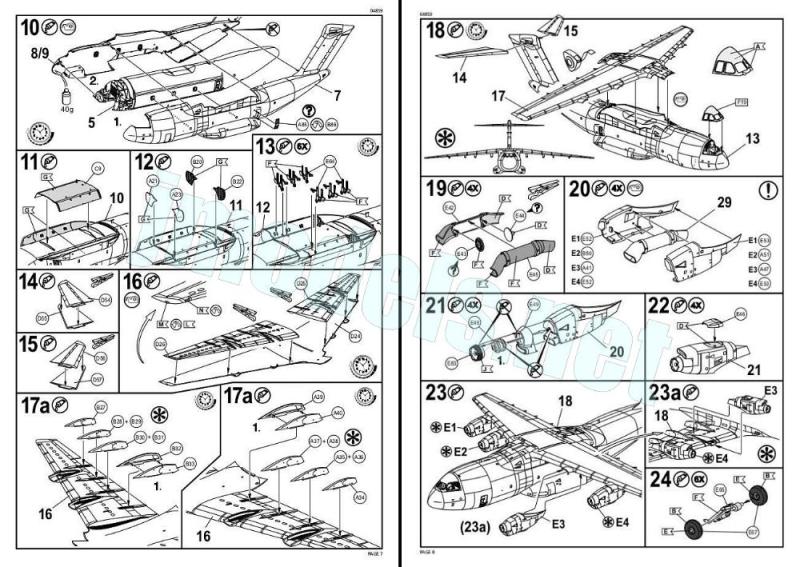
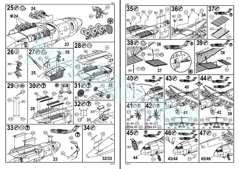
Pegado el fuselaje, la atención se centra en la zona ventral y en las bodegas del tren de aterrizaje principal, cuya parte delantera tiene las luces de aterrizaje grabadas, pero no transparentes. En esta zona tenemos un panel situado entre los dos espacios y piezas para cerrar los huecos por delante y detrás. Llegados a este punto del montaje, y sólo si queremos colocar las ruedas desplegadas, es aconsejable decidir cómo vamos a montar el tren de aterrizaje. Este se compone a cada lado por tres patas con ruedas dobles en cada una y una pieza que simula los brazos extensores. De acuerdo con las instrucciones, primero se pegan los brazos en la bodega y luego se suman las patas y las ruedas, que tienen las llantas bien definidas y el sistema de frenos en el lado interno.
No lo he comprobado, pero se me ocurre que podría resultar complicado introducir la última de las tres patas en el reducido espacio interno de la bodega. Como alternativa, si esto ocurre, se puede montar el conjunto de cada rueda por separado y pegarlo después en la bodega. El lado externo de cada bodega tiene un par de marcas grandes pero leves que posiblemente no haga falta rellenar al cubrirlas las ruedas. Montado el tren de aterrizaje, la parte central del fuselaje situado entre los pozos se cubre con una pieza que reproduce la superficie externa.
Las tapas vienen unidas en una pieza para facilitar el montaje del avión en vuelo, de este modo hay que cortarlas por la mitad si nuestra opción es diferente. Esto mismo sucede con las puertas del tren delantero, que se compone de una pata, dos ruedas bien detalladas y un brazo extensor separado.
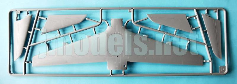
Las alas constan de tres piezas, con las mitades inferiores separadas de la superior. El detalle de las superficies es notable, destacando la nitidez de los flaps, algunas tomas, el tubo de salida de la unidad de potencia auxiliar (APU) y las luces de las puntas y de formación. Los carriles carenados para extender los flaps (FTF) vienen separados.
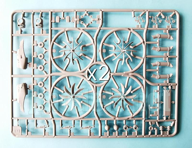
Las góndolas de los motores están dispuestas en mitades con el frontal aparte y la toma inferior abierta. La parte inferior lleva otra toma por separado. El interior de cada góndola posee un pequeño tubo unido a la toma frontal con la salida del escape en la parte trasera. Entre las mitades del tubo hay un par de piezas redondas que simulan el compresor delante y la turbina detrás.
Las hélices son finas y deben tratarse con delicadeza, especialmente al cortarlas de los bastidores, porque se parten con solo mirarlas. Con gran acierto, Revell eligió proporcionarlas dobles, cada juego con las palas en una posición, en lugar de cometer la burrada de separar las palas (nada menos que ocho por hélice) para que las pegue el modelista. El buje y la placa base son piezas aparte.
Las superficies verticales de cola están moldeadas con el fuselaje y los estabilizadores van unidos mediante lengüetas a cada lado. Los timones están bien grabados, especialmente los de profundidad. En la parte superior falta la luz anticolisión.
La hoja de calcas dice estar impresa en Italia, como es costumbre. Corre la especie entre los modelistas, casi una leyenda urbana, de que su verdadero fabricante es Cartograf. Vaya usted a saber, lo cierto es que la hoja tiene muy buen aspecto. Contiene insignias nacionales, logotipos, códigos y matrículas, líneas del fuselaje y alas, además de numerosos estarcidos. Los motivos muestran acabado fino y brillante, buena nitidez y registro, y no tienen exceso de soporte.
Las instrucciones están impresas en blanco y negro en un folleto A4 de doce páginas que muestran una introducción histórica con datos técnicos, una lista de colores con equivalencias de pinturas del fabricante, 47 capítulos de montaje y dos páginas y media de perfiles.
Las ilustraciones del montaje son claras en general, pero las secuencias resultan un tanto profusas y es necesario estudiarlas muy bien, eligiendo primero la configuración deseada de las tres posibles.
La maqueta incluye alternativas para dos aviones militares y uno de Airbus. Las tres opciones no son tales salvo en las calcas, ya que todas llevan idéntica librea de gris. A este color habría que darle un tono claro suficiente para contrastar las calcas que reproducen las marcas grises “A400M” en la versión de Airbus. Afortunadamente, hay varios juegos de calcas en el mercado para cambiarle la nacionalidad. En España son destacables las de la marca Series Españolas.
Valoración
Esta es una buena pieza para los amantes de los cargueros del peso pesado, con acertadas opciones de montaje y posibilidades de ser la estrella de una escena con vehículos y carga alrededor. Aunque le falta algunos detalles mínimos y Revell la complicó con el doble fuselaje, la maqueta tiene en general un detalle notable para esta escala mínima. Es muy recomendable hacer espacio en la vitrina.◊


The kit
Before this kit, Revell released the A400M in the 1/72 scale. I remember once seeing a guy leaving a shop with that scale kit in his hands, and he was having serious trouble holding the box because of its size. That’s what happens when you don’t carry a handcart beforehand, especially if you’re insatiable, of course. The model I’m discussing today is 32 cm long with a wingspan of 29.3 cm, according to the manufacturer. With that size, you can imagine the size of its elder brother. In either case, you’ll need to make quite a bit of space where you’re going to display them.
So far, this kit has only been reissued once, in 2024 (ref. 03789), and it also came with a Panavia Tornado as an escort, unlike the 1/72 scale A400, which has had several reboxes with shorter intervals between them.
The box contains six sprues of gray parts, a clear sprue, the decal sheet, and the instructions. The parts are well molded and generally show good detail, with some plastic nodes here and there. Panel are mostly engraved, but there are also a few well-represented raised lines. The panel engraving is so fine and precise that it will be difficult to make it visible after painting over some areas, such as the wings. This is especially true with a color as dark as the standard A400M livery. There are numerous negative ejector pinholes throughout. Apparently, almost all of them should be in hidden areas. If not, I will indicate them in their spots.
Assembly allows the model to be finished in three ways: in flight or on the ground with the access and cargo doors open or closed. Paint finishes are identical, differing only in the decals, which allow for the reproduction of two military aircraft (Luftwaffe and French Air Force) and the first test aircraft built to the final production specifications by Airbus.
Review
On page 5 of the instructions, we find the three assembly options for the kit. The first chapter indicates the cuts in the cargo bay floor and the lower tail pieces to build the loading ramp open.
The fuselage halves come in four pieces, which seems to complicate assembly. Two of these pieces reproduce the exterior, and the other two the interior, except for the cockpit and the cargo compartment floor, which are separate. The cockpit comprises a floor with the instrument panel detailed with decals, the center console, two side consoles, and seats for three crew members. Behind the cockpit are four parallel bulkheads arranged transversely, detailed with panels, and two bunks. The loadmaster’s seat is located in the forward part of the cargo hold floor piece, and the stairs to the flight deck are in one of the bulkheads.
The inner fuselage sides are finely reproduced and contain the troop seats, as well as a very well-defined, raised rib pattern in the rear section. The cargo hold floor is detailed with numerous cargo tie-down points, clearly visible despite their small size. If the loading ramp is posed open, the detached rear section includes a pair of hydraulic arms, a ramp extension, and two extendable stabilizing legs. However, the cargo crane is missing.
The inner fuselage halves can be glued together once the cockpit and ramp are finished in the chosen configuration. On their outer side, these pieces show plenty of marks and the window gaps with raised edges that fit into the openings in the outer fuselage. Some marks are close to the windows but don’t affect them.
Before gluing this internal assembly to the outer fuselage sides, you need to add the forward wheel well, a 40g ballast inside the fuselage nose, and the windows. If the fit is good (I haven’t checked it), the window frames should align, and the canopy should fit easily into the fuselage’s side notches.
The outer fuselage halves are molded with some fins and electronic devices on the top and bottom, plus others in separate parts. The canopy has a reasonable thickness, and the windows are well represented. The refueling probe is separate. The side access door can be positioned open and has the stairs molded in the part. The side doors located behind the wings, designed for paratroopers, are closed, but the internal opening is represented. The exterior can be optionally detailed with the deflector door, a nice touch.
With the fuselage glued in place, attention now focus on the ventral area and the main landing gear bays. The front of these bays has engraved landing lights, but they are not clear parts. The belly has a panel between the two bays and pieces to close the gaps inside the bays at the front and rear. At this stage of assembly, and only if you intend to build the model with the wheels down, you need to decide how you want to assemble the landing gear. Each side consists of three legs with double wheels and a piece for the folding arms. According to the instructions, the arms are glued inside the bay first, and then the legs and wheels are attached. The wheels have clearly defined rims and the brakes on the inner side.
I haven’t tested it, but I think that fitting the last of the three legs into the limited space inside the bay might be tricky. As an alternative, if this is the case, each wheel assembly can be built separately and then glued to the bay. The inner side of each sponson has a couple of large but shallow pin marks that probably won’t need filling once the wheels are in place. With the gear finished, a piece with the central fuselage section is attached between the bays.
The bay doors come as a single piece to ease assembly of the model in flight; so, they need to be cut in half if you choose a different configuration. The same applies to the doors of the nose landing gear, which consist of a leg, two nice wheels, and a separate extension arm.
The wings are made up of three pieces, with two lower halves. Surface detail is quite good, particularly the sharpness of the flaps, some intakes, the auxiliary power unit (APU) exhaust pipe, and the wingtip and formation lights. The flap extension rails (FTF) are separate.
The engine nacelles are arranged in halves, with the front section separate and the lower intake open. The lower section has another separate intake. Inside each nacelle is a small duct connected to the front intake, with the exhaust outlet at the rear. Between the duct halves are a pair of round pieces for the compressor in front and the turbine behind.
The propellers are thin and need to be handled with care, especially when cutting them from the sprues, because they can break easily. Revell wisely chose to provide them in pairs, each set with the blades in a different position, rather than making the mistake of separating the blades (no fewer than eight per propeller) for the modeler to glue together. The hub and base plate are separate parts.
The vertical tail surfaces are molded with the fuselage, and the stabilizers are attached with tabs on each side. The rudders are well engraved, especially the elevators. The anti-collision light is missing from the fin tip.
The decal sheet is printed in Italy, as usual with Revell. There’s a rumor among modellers, almost an urban legend, that its true manufacturer is Cartograf. Who knows? The fact is, the sheet looks very good. It contains national insignia, logos, codes and registrations, fuselage and wing lines, as well as numerous stencils. The decals have a fine, glossy finish, good sharpness and registration, and no surplus carrier film.
The instructions are printed in black and white in a 12-page A4 booklet that includes a historical introduction with technical data, a color list with Revell paint matches, 47 assembly chapters, and two and a half pages of profiles.
The assembly illustrations are generally clear, but the sequences are busy and need careful study, first selecting the configuration from the three available.
The kit includes options for two military aircraft and one Airbus test machine. The three options look the same except for the decals, as they all feature a gray livery. This gray should be lightened to contrast the decals that reproduce the dark gray «A400M» markings on the Airbus version. Fortunately, several decal sets are available to change the aircraft’s nationality. In Spain, the Series Españolas brand offers a particularly nice sheet.
Conclusion
This is a great kit for fans of heavyweight freighters, with good assembly options and the potential to be the star of a scene with vehicles and cargo around it. Although it lacks a few minor details and Revell complicated things with the double fuselage, the kit is generally remarkably detailed for this small scale. Making room for it in your cabinet is highly recommended.◊
Publicado – Published: 8 / 2026
©www.jmodels.net


Debe estar conectado para enviar un comentario.