
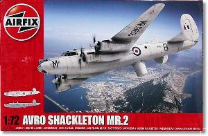
De un vistazo – Quick look
MATERIAL Y PIEZAS
MEDIA & PARTS:
- Plástico inyectado (239 piezas), plástico transparente (28 piezas). Incluye 2 figuras.
- Injected plastic (239 parts), clear plastic (28 parts). Two figures included.
CALCAS – DECALS:
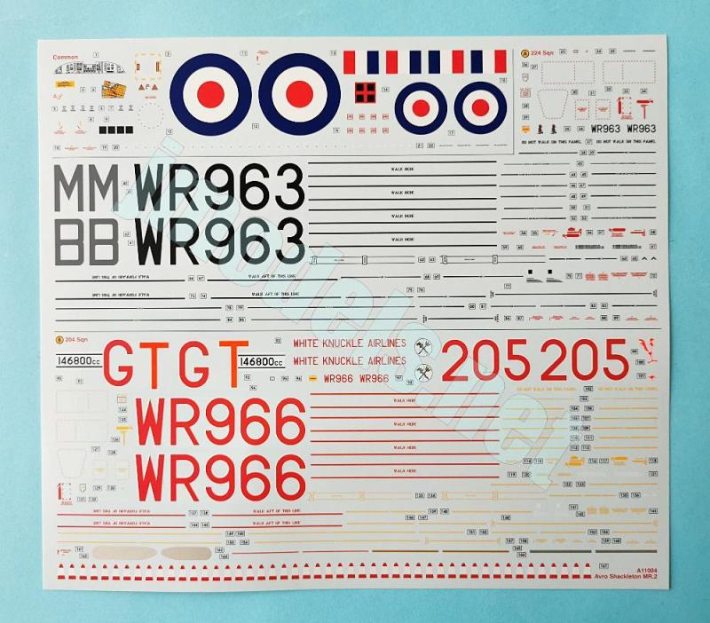
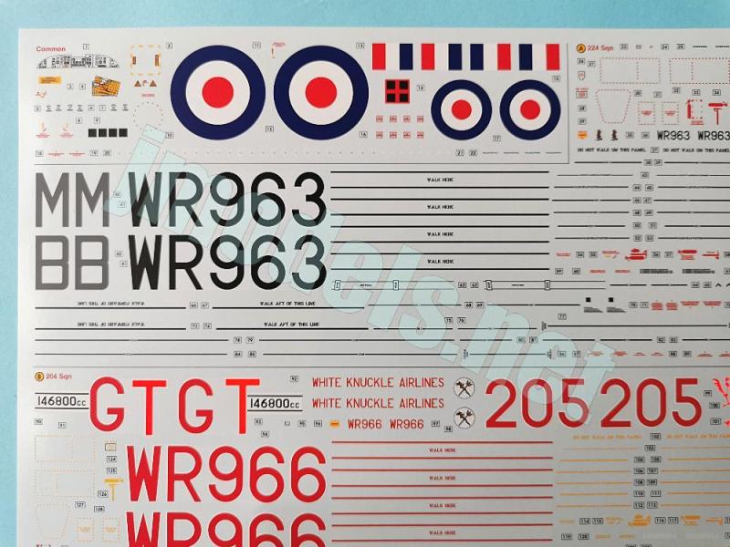
- Impresas por Cartograf en una hoja de gran tamaño. Contiene insignias nacionales, matrículas, códigos, el panel de instrumentos, líneas de no pisado y multitud de estarcidos. Apariencia fina y brillante, gran nitidez, buena saturación de color. Soporte bien cortado alrededor de cada motivo.
- Printed by Cartograf in a large sheet. It contains British roundels, registrations, codes, the instrument panel, no step lines and dozens of stencils. Thin and glossy finish, very good sharpness and color saturation. Carrier film cut close around the decals.
OPCIONES – OPTIONS:
- Avro Shackelton MR.2. Royal Air Force North Front. No. 224 Squadron. Gibraltar. September 1967.
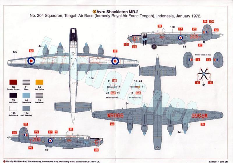
- Avro Shackelton MR.2. Royal Air Force. No. 204 Squadron. Tengah Air Base (Indonesia). January 1972.
INSTRUCCIONES – INSTRUCTIONS:
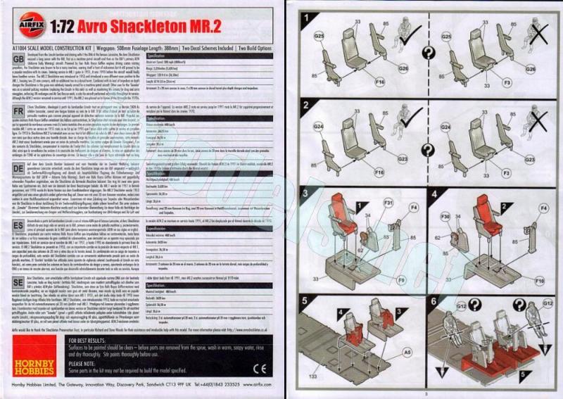
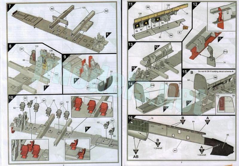
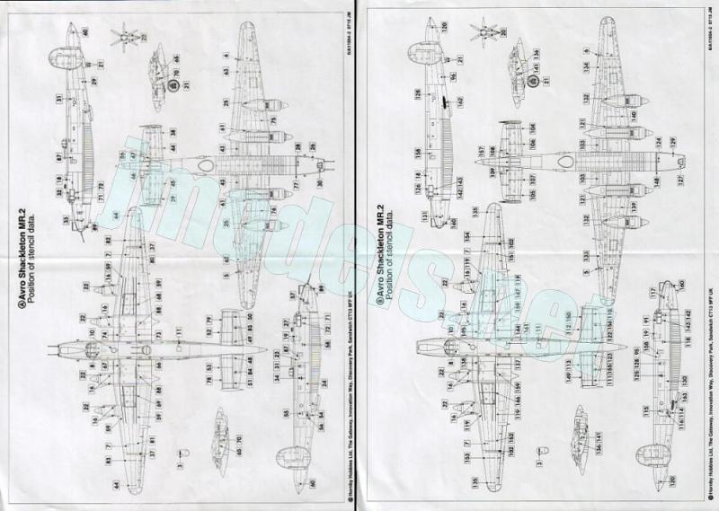
- Folleto A4 de 20 páginas impreso en blanco, negro y color. Contiene una introducción histórica con datos técnicos y 113 secuencias de montaje. Dos hojas separadas de formato A3 impresas en color y blanco y negro respectivamente sobre papel satinado muestran perfiles y códigos de pinturas de Humbrol así como perfiles para colocar los estarcidos.
- 20-page A4 booklet printed in black, white and color. It contains a historical introduction with technical data and 113 assembly chapters. Two separate A3 sheets printed in color and black and white respectively on satin paper show profiles and Humbrol paint codes as well as profiles to set the stencils.
LO MEJOR – THE BEST:
- Buen detalle interno y externo. Alternativas de construcción. Piezas transparentes muy finas, aunque delicadas. Extensa hoja de calcas.
- Nicely detailed inside and outside. Assembly choices. Very thin clear parts, though delicate to handle. Extensive decal sheet.
LO PEOR – THE WORST:
- Marcas en el interior del fuselaje. Cierto equipamiento interno podría estar mejor definido.
- Marks inside the fuselage. Some internal equipment could be better defined.
VALORACIÓN – CONCLUSION:
- Posee amplias ventajas respecto a sus limitados inconvenientes. Por su tamaño y buen detalle en general podría valer a quienes se dedican a escalas mayores.
- It has significant advantages that outweigh its few drawbacks. Its size and generally good detail make it suitable for fans of larger scales.

La maqueta
Durante décadas desde 1967 el molde de FROG fue el único del Shackelton en la escala 1/72. Como era habitual, la maqueta tuvo muchas reediciones en otras marcas, como Revell y Hasegawa. En 2015 Airfix lanzó la maqueta del MR.2 (versión de reconocimiento marítimo) que me ocupa hoy, seguida de otra con la versión AEW (Airborne Early Warning, Alerta Aérea Temprana) (referencia A11005). En este 2026 Airfix anuncia una reedición con las dos versiones en una sola caja (referencia A11013). Como no hay dos sin tres, Revell lanzó en 2016 y 2019 su molde propio en dos cajas con las versiones MR.3 (Phase 2 y 3) y AEW.2.
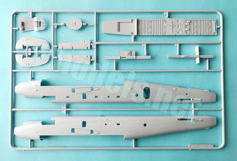
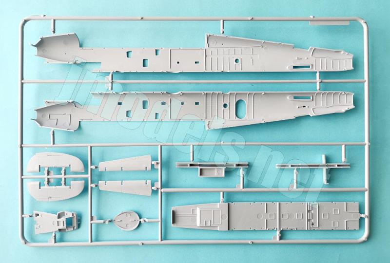
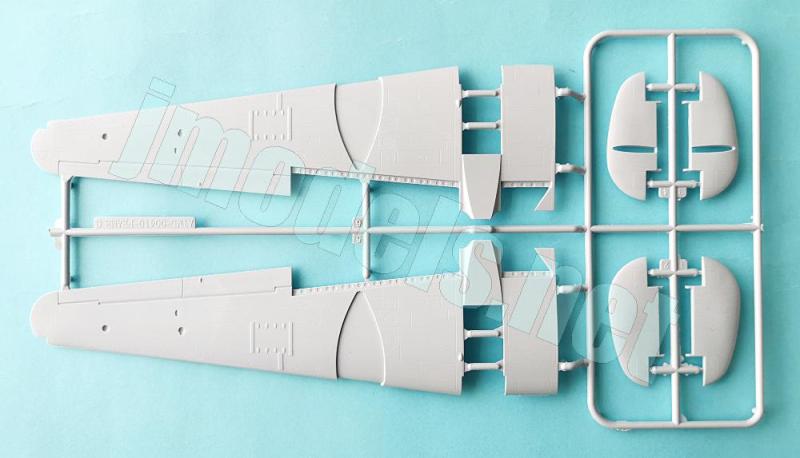
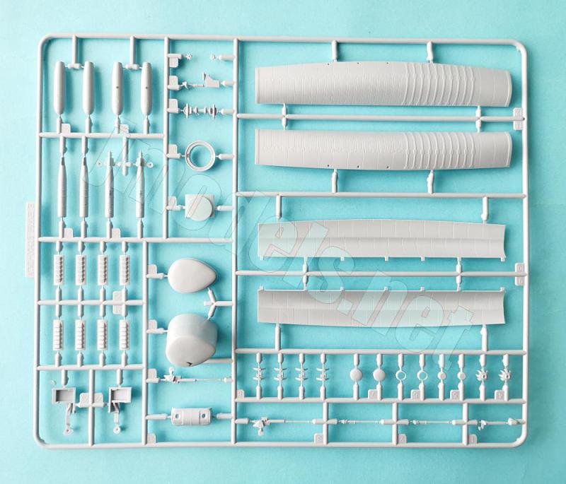
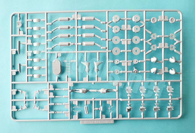
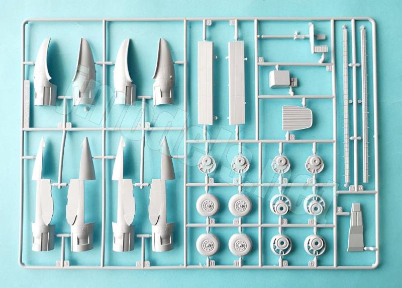
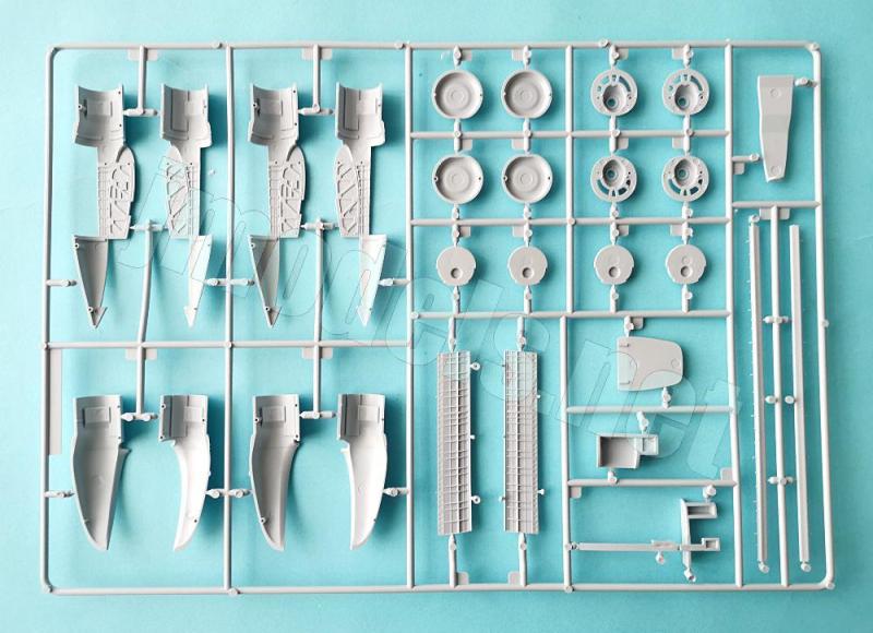
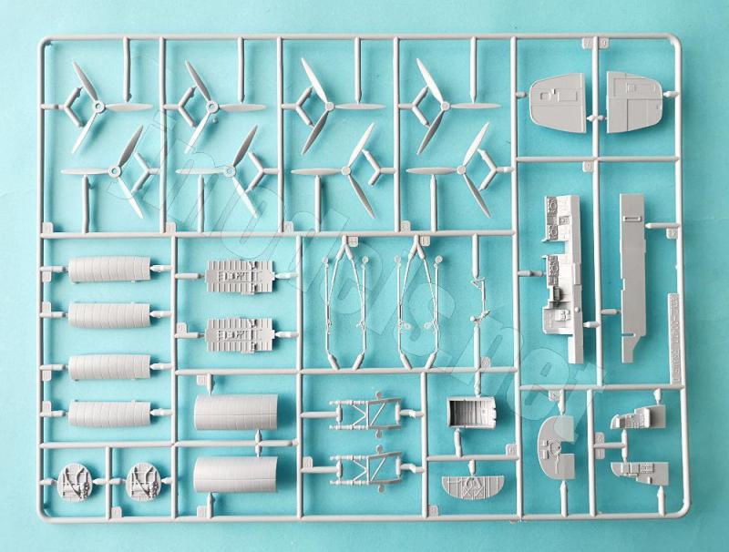
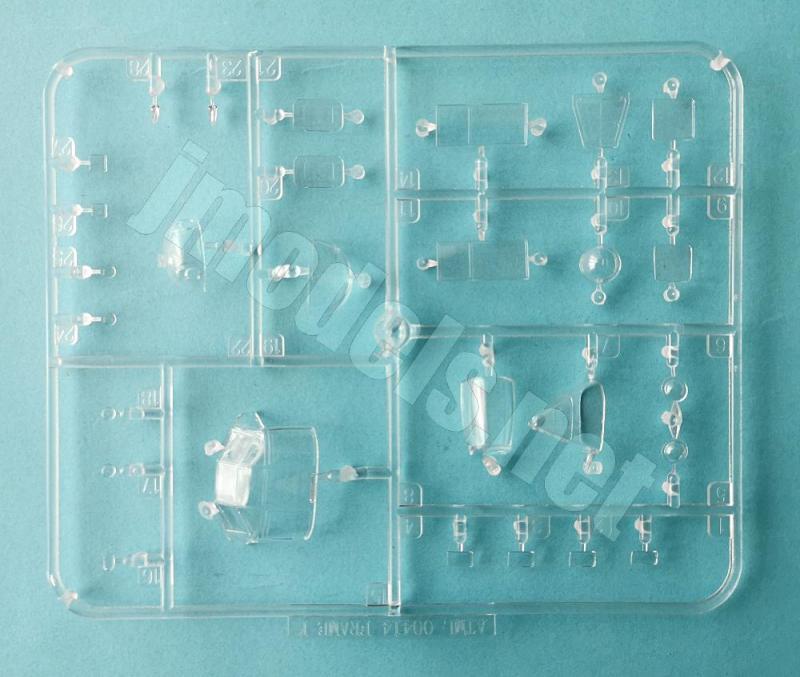
Dentro de la caja de gran tamaño encontramos nueve bastidores de piezas, uno de ellos transparente, un amplia hoja de calcas y el manual de instrucciones. El moldeado de las piezas es el habitual de Airfix, sin deformaciones en las piezas, algunas líneas de molde en determinados elementos, como las ruedas de cola, y marcas de eyector abundantes en el interior del fuselaje. Algunas de estas marcas afectan al detalle de la estructura reproducida en las piezas, aunque en zonas no visibles tras cerrar el fuselaje. Las de los lados de la carlinga será inevitable taparlas por precaución, pero son muy poco profundas.
El grabado de las líneas de paneles y distintos detalles en las superficies de las alas y el fuselaje es muy fino y convincente. No tiene nada que ver con el de otras maquetas donde el fabricante se excedió bastante al representarlo.
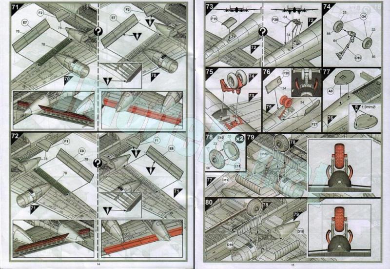
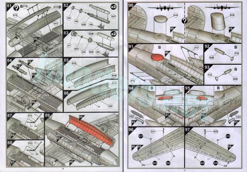
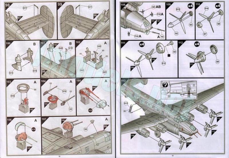
Obviamente, la construcción de un avión de buen porte como el Shackleton y con bastantes elementos en su interior no es cuestión de un fin de semana y requiere más paciencia y método que en otras maquetas más simples. El montaje, bien diseñado, ofrece varias alternativas además de la posibilidad de colocar el tren de aterrizaje plegado. Algunas de ellas son comunes a los dos aviones representados en las instrucciones y otras específicas de cada uno. Las describiré en su lugar pertinente.
Las opciones de pintura son diferentes y alternan el mismo patrón de camuflaje, básicamente compuesto de gris y blanco.
Reseña
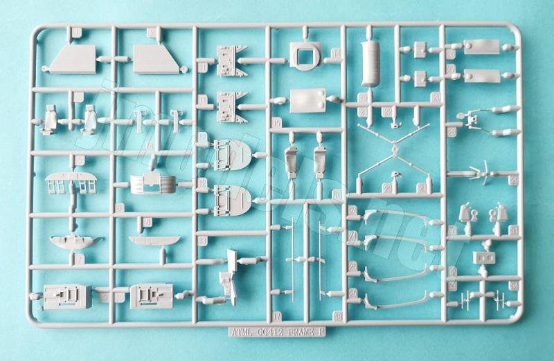
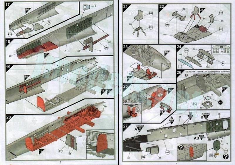
Las zonas reproducidas en el interior del fuselaje son el puesto frontal del artillero y del bombardero, la carlinga, la zona de los operadores de radares, sensores y demás cacharros electrónicos, la zona de descanso de los tripulantes y el puesto de observador en la punta trasera. La estructura de los lados interiores del fuselaje únicamente está representada en la dos últimas zonas. Casi la totalidad del interior dispone de un único suelo donde se van añadiendo los elementos de las diferentes zonas.
El puesto frontal contiene un suelo con varios instrumentos separados en la parte trasera, el asiento, el afuste de los cañones proeles, con la mira añadida tras cerrar el fuselaje, y el puesto de bombardero por debajo del asiento mencionado con el hueco del panel acristalado justo por delante, que pegaremos una vez cerrado el fuselaje.
La carlinga centa con dos suelos separados para los pilotos con sus respectivos asientos, controles y consolas laterales. Los asientos tienen alternativas, con poca diferencia entre ellos, a fin de poder adaptar las fguras de los pilotos si queremos usarlas. Para esto también hay que recortarles la piernas por debajo de las rodillas, una crueldad innecesaria para lo poco que se van a ver. El panel está moldeado con los pedales y los instrumentos son de calca y tiene una cubierta separada que se pega tras cerrar el fuselaje.
Por detrás de puesto de la carlinga tenemos dos mamparos con algunas marcas en la parte delantera y los instrumentos, consola y asiento del ingeniero de vuelo. Los instrumentos no son tan abundantes como en la realidad y no llevan calca, pero dan avío. En el lado opuesto aparece el puesto del navegante, también con su mesa, asiento y controles muy parcialmente representados. Sobre la mesa podemos colocar un mapa de calca doblado para darle vidilla.
La parte central contigua a la anterior lleva cuatro asientos y las consolas de los operadores de sistemas moldeadas en una pieza. Las pantallas de los radares son lo mejor, porque los demás instrumentos muestran un detalle básico, aunque parece suficiente para la escala y el lugar oculto que ocupan. Esta zona central la cortan dos travesaños para sujetar las alas, elementos irreales pero necesarios en la maqueta.
Por detrás del área descrita hay un hueco vacío, limitado por un mamparo que da acceso a la zona de observación, detallada con un par de asientos y una especie de consola sin definir en lo que debería ser la cocina en el lado opuesto. Sólo se aprecia con claridad el estante de almacenaje de bengalas. Otro mamparo en la parte posterior cierra este espacio.
La punta posterior del fuselaje alberga dos piezas, una de ellas el pozo de las ruedas traseras. El acristalamiento externo está representado en una pieza muy fina, con formas aparentemente correctas y el marco grabado sin relieve.
Antes de unir las mitades del fuselaje hay que taladrar varios agujeros en varios puntos, según el aparato concreto que pretendamos hacer, para pegar piezas en dichos lugares posteriormente. También hay que pegar la puerta lateral de acceso, que podemos dejar abierta, y una pieza en el lado derecho del compartimento del bombardero que simula el equipo eléctrico y la radio frontal. El avión de la Escuadrilla 204 lleva un panel acristalado como salida de emergencia en lugar de la torreta artillada.
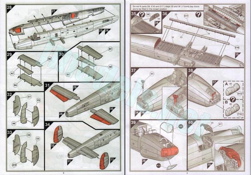
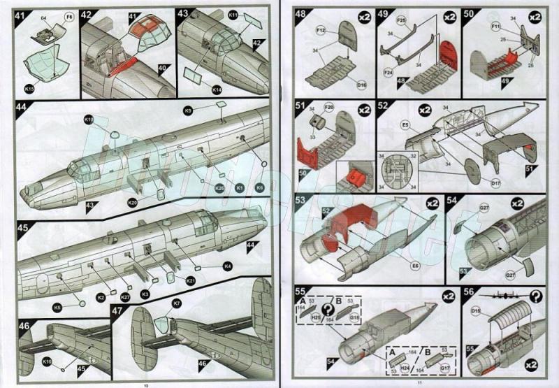
Unido el fuselaje, se pegan todas las ventanillas laterales, los acristalamientos del morro así como la cúpula de obervación del navegante. La cubierta de la carlinga tiene dos paneles laterales separados y un panel con instrumentos añadido en su lado interno. Todas las piezas transparentes son muy finas y presentan una apariencia frágil.
El detalle exterior del fuselaje en el avión de la Escuadrilla 224, descrito de proa a popa, comprende un panel en el morro con el mecanismo de elevación de los cañones y los tubos de las armas separados; pequeñas antenas a los lados del morro y la parte inferior; una antena de lágrima y la torreta dorsal, compuesta de una base con asiento, el afuste, un anillo giratorio, los cañones aparte y la cubierta en dos mitades. Como alternativa, el avión de la Escuadrilla 204 no lleva armamento en el morro ni torreta y las antenas dorsales son distintas, destacando por su tamaño la antena de contramedidas electrónicas.
Las piezas comunes para las dos versiones son el radomo ventral que se puede colocar subido o bajado, en este último caso solamente si el avión lo representamos en vuelo, más las tomas de los intercambiadores de calor y dos antenas de carril a los lados del radomo.
Me parece un acierto que Airfix aprovechase el suelo interno para representar el fondo de la bodega de armamento por la otra cara. El detalle es intrincado y está limpio de marcas. Los paneles situados por delante y detrás también muestran muy buena factura. Las compuertas van colocadas sobre sendos perfiles unidos a los lados del hueco y podemos colocarlas cerradas o abiertas. En este caso último las piezas son dobles, tal vez por eso son tan finas. Ambas llevan paneles bien grabados en las superficies y dos finos brazos de apertura separados. En la bodega podemos colocar dos torpedos Mk.30 y dos Mk.44.
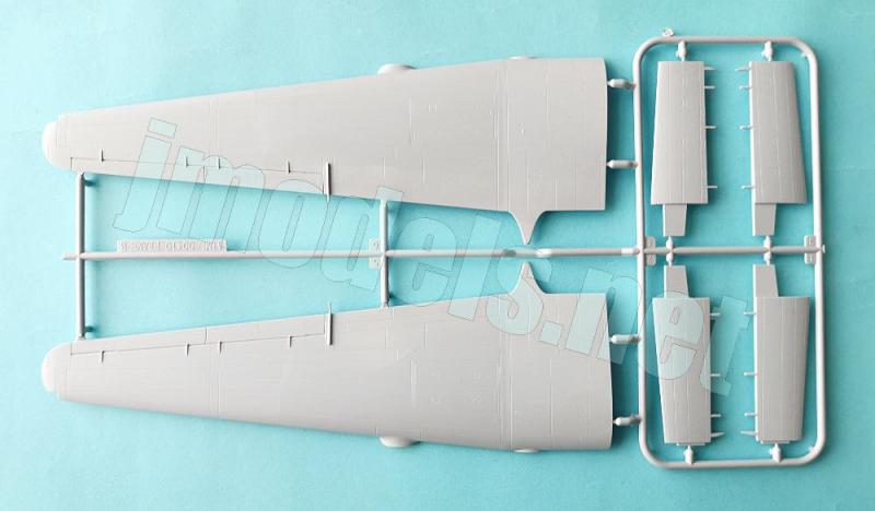
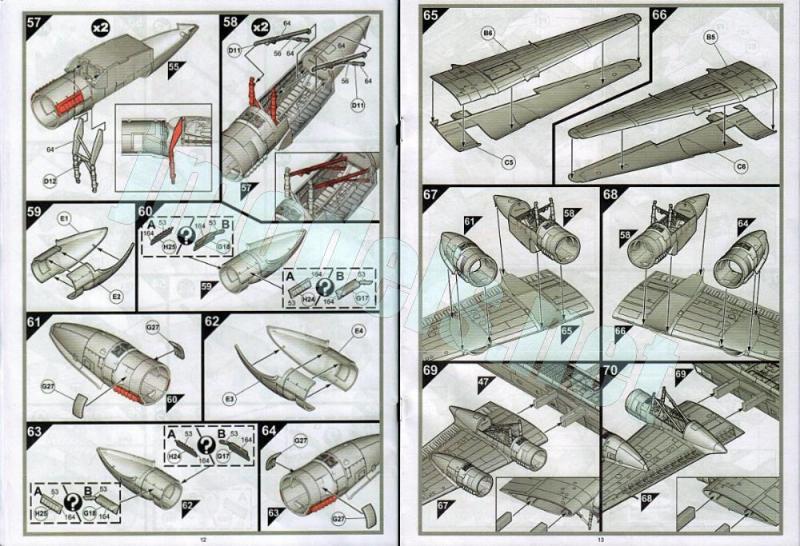
Las alas están separadas en mitades. Los alerones están bien grabados y los flaps pueden colocarse cerrados o abiertos gracias a un interior bien definido y sin marcas. Elementos separados son las luces de las puntas y las de aterrizaje (ambas transparentes) y los tubos Pitot. Las alas van encastradas en los travesaños laterales del fuselaje, lo que debe darles la rigidez y firmeza convenientes.
Las góndolas de los motores vienen en dos mitades unidas a los capós de los motores. Las externas llevan simplemente dos paneles y los escapes separados. Los escapes son alternativos según el avión concreto que elijamos. Las góndolas interiores incluyen los pozos de las ruedas. Airfix no escatimó el detalle interno y proporciona un fondo y dos lados. El detalle interior es muy bueno e incluye un depósito, imagino que para el líquido hidráulico. Si dejamos las ruedas bajadas, emplearemos las tapas del pozo abiertas, ambas bien grabadas y limpias por los dos lados. Las patas del tren de aterrizaje tienen la amortiguación marcada y los brazos extensores son muy finos y delicados de manipular. Las ruedas están separadas en mitades y se pegan al extremo de la horquilla sin necesidad de hacerlo a presión. Las llantas están bien grabadas y el tamaño de los neumáticos le ha dado a Airfix espacio bastante para grabar la banda de rodadura.
La cara frontal de los motores está separada en una pieza que muestra la toma inferior hueca. Las hélices van superpuestas unas a otras una vez pegadas a sus respectivas secciones del cono común a ambas. En la parte posterior llevan una placa base y el eje introducido por detrás del frontal del motor. A las palas no cabe ponerles tacha porque son bastante finas y carecen de restos de plástico.
Todas las superficies de cola están divididas en mitades con un grabado convincente en las aletas compensadoras. Los timones separados son de una pieza y van pegados sobre las bisagras. Las instrucciones no indican que puedan colocarse girados, pero con pequeñas modificaciones podría lograrse.
El tren aterrizaje auxiliar comprende una pata con la suspensión bien definida, dos ruedas, un brazo hidráulico aparte y una base pegada en el interior del pozo, que muestra un detalle bastante nítido. Las ruedas presentan las llantas detalladas, pero lo neumáticos son lisos y hay una fina línea de molde en su contorno.
La extensa hoja de calcas, impresa por Cartograf, contiene insignias nacionales, matrículas, códigos, el panel de instrumentos, líneas de no pisado y multitud de estarcidos. Los motivos poseen una apariencia fina y brillante, gran nitidez y buena saturación de color. El soporte excedente es mínimo al estar bien cortado alrededor de cada calca.
El manual de instrucciones consta de veinte páginas impresas en blanco, negro y color en formato A4. Contiene una introducción histórica con datos técnicos y 113 secuencias de montaje. Dos hojas separadas de formato A3 impresas en color y blanco y negro respectivamente sobre papel satinado muestran perfiles y códigos de pinturas de Humbrol así como perfiles para colocar los estarcidos.
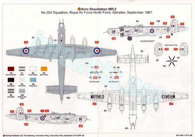
Las opciones para pintar el modelo ofrecen libreas navales de gris y blanco, pero con los colores invertidos y distribución diferente que les da un tanto de variedad.
El sitio web thegrowler.org.uk ofrece información específica de cada uno de estos aviones que no coincide fielmente con la que proporciona Airfix. El MR.2 con matrícula WR663 hizo su primer vuelo en marzo de 1954. En octubre de ese año fue destinado a la Escuadrilla 224 de Gibraltar, donde en 1956 recibe el código M en el morro. Tras varias modificaciones y actualizaciones realizadas en Gran Bretaña se le asigna la escuadrilla 210 en 1960 y posteriormente otras más. En 1971 comienzan los trabajos para convertirlo en un AEW.2 que terminan el año siguiente. Este aparato se conserva hoy en el Aeropuerto Bagington de Coventry (Reino Unido) a cargo de la Shackleton Preservation Society. Además de estos datos que no coinciden con los de la maqueta, la Escuadrilla 224 fue disuelta en octubre de 1966, por eso nunca pudo operar el avión en tal fecha como septiembre de 1967 como señala Airfix.
La otra alternativa, matriculada WR966, realizó su primer vuelo en abril de 1954. La Escuadrilla 204 lo recibió en mayo de 1961, pero posteriormente fue transferido a otras unidades, además de recibir diversas modificaciones y actualizaciones que lo convirtieron en un T.2 (versión de entrenamiento de radar). Fue luego enviado a la Escuadrilla 205, donde recibe el código G, y de ahí a la 204 destacada en el Lejano Oriente en noviembre de 1971. Al poco tiempo, el aparato es devuelto al Reino Unido, a donde llega el 10 de enero de 1972 para ser luego declarado no apto para el servicio y desguazado en junio de 1973. El avión que vemos en los perfiles de la maqueta debió ser un entrenador, de ahí posiblemente la T de su código en el morro, y desde luego estuvo pocos días en servicio en enero de 1972.
Valoración
Airfix hizo por fin una maqueta del Shackleton a la altura de los tiempos, tras décadas sin más alternativas que el obsoleto molde de FROG. Las cualidades provechosas de la maqueta aventajan ampliamente las menos acertadas, que se limitan al interior del fuselaje y son prácticamente imperceptibles.
No conozco a fondo la maqueta de Revell, pero cabe imaginar que esta debe competir bien con ella a juzgar por su notable detalle general y de un proceso de construcción bien estudiado. Dado su tamaño, las posibilidades de montaje y la amplitud de la hoja de calcas, puede ser una opción atractiva incluso para quienes suelen dedicarse a escalas mayores.◊

The kit
For decades, since 1967, the FROG kit was the only one of the Shackleton in the 1/72 scale. As usual with most kits of the time, this one also had many reboxes from other brands, such as Revell and Hasegawa. In 2015, Airfix released their MR.2 (maritime reconnaissance version) kit followed by another boxing with the AEW (Airborne Early Warning) version (reference A11005). In 2026, Airfix announced a reissue with both versions in a single box (reference A11013). And, as they say, good things come in threes, Revell released their own kit in 2016 and 2019 in two different boxes containing the MR.3 (Phase 2 and 3) and AEW.2 versions.
Inside the large box, we find nine sprues of parts, one of them clear, a large decal sheet, and the instruction manual. The molding of parts is typical of Airfix, with no blemishes, seam lines on some pieces such as the tailwheels, and numerous ejector marks inside the fuselage. Some of these marks affect the structural detail in non visible spots once the fuselage is closed. Those on the cockpit sides will inevitably need to be covered as a precaution, but they are very shallow.
The engraving of panel lines and details on the wings and fuselage is very fine and convincing, and certainly has nothing to do with the deep trenches found on other kits the brand released time ago.
Obviously, building a large aircraft like the Shackleton, with its numerous internal components, is not a weekend project and needs more patience and a methodical approach than simpler kits. The well-designed assembly offers several alternatives in addition to posing the landing gear folded. Some of these alternatives are common to both aircraft shown in the instructions, while others are specific to each. I will describe them below.
Paint choices are different and alternate between the same camouflage pattern, which is basically gray and white.
Review
The areas reproduced inside the fuselage are the forward gunner’s and bomb aimer’s positions, the cockpit, the area for radar operators, sensors, and other electronic equipment, the crew rest area, and the observer’s station at the rear. The structure of the fuselage interior sides is only represented in the last two areas. Almost all the interior has a single floor to add the pieces of the different compartments.
The forward station includes a floor with several instruments separated at the rear, the seat, the forward cannon mount (with the sight added after the fuselage is closed), and the bomb aimer’s station below the gunner’s seat, with the opening for the glazed panel just in front, which is attached once the fuselage is closed.
The cockpit has two separate floors for the pilots, each with its respective seat, controls, and side console. The seats have alternative pieces, with little difference between them, to allow for the fitting of the pilot figures if desired. For this, you also have to cut off their legs below the knees, an unnecessary cruelty considering how little they’ll be visible. The panel is molded with the pedals, and the instruments are decals. It has a separate shroud that is attached after the fuselage is closed.
Behind the cockpit, we have two bulkheads with some marks on the front sides, and the flight engineer’s instruments, console, and seat. The instruments aren’t as numerous as in reality and have no decals, but they do the job. On the opposite side is the navigator’s station, also with its table, seat, and controls, which are only partially represented. A folded decal map can be added on the table to spice up the spot.
The next central section contains four seats and the systems operators’ consoles, molded as a single piece. The radar displays are the best feature, as the other instruments show only basic detail, although it could be enough considering the scale and the fact they won’t be seen after closing the fuselage. This central area is provided with two crossmembers to insert the wings. These are unrealistic but necessary elements in the model.
Behind this area is an empty space, defined by a bulkhead with an access to the next compartment. This area is detailed with a couple of seats and an undefined piece that should be the galley on the opposite side. Only the flare stowage rack is clearly visible. There is another bulkhead at the rear.
The rear fuselage tip houses two parts, one of which is the wheel well. The external glazed tip is represented as a very thin piece, with seemingly accurate shapes and a flat, engraved frame.
Before joining the fuselage halves, you need to drill holes on the fuselage, depending on the specific aircraft you are building, to later attach some parts. The side access door, which can be posed open, is also attached, along with a piece on the right side of the bomb aimer’s compartment for the electrical equipment and the front radio. The 204 Squadron aircraft has a glazed panel for the ditching exit instead of the gun turret.
Once the fuselage is closed, all the side windows, the nose glazing, and the navigator’s astrodome are attached. The cockpit canopy has two separate side windows and an overhead instrument panel added to its inner side. All the clear parts are very thin and look fragile.
The fuselage exterior detail on the 224 Squadron aircraft, described from bow to stern, comprises a panel on the nose with the gun elevating mechanism and separate gun barrels; small antennas on the sides of the nose and the underside; a teardrop antenna; and the dorsal turret, consisting of a base with a seat, the mount, a rotating ring, the separate guns, and the two-part canopy. Alternatively, the 204 Squadron aircraft has no nose armament or turret, and the dorsal antennas are different, notably the electronic countermeasures antenna, which is particularly large.
The common parts for both versions are the ventral radome, which can be positioned up or down (the latter only if the aircraft is being represented in flight), plus the heat exchanger air intakes and two rail antennas on either side of the radome.
I think it was a great idea of Airfix to use the internal floor to represent the bottom of the bomb bay on the other side. Detail is intricate and free from marks. The panels at the front and rear are also very nicely detailed. The hatches are attached to separate profiles on the sides and can be displayed open or closed. In the first case, each door has a piece per side, which is the reason why they are so thin. Both versions have well-engraved panels on their surfaces and two thin, separate hydraulic jacks. The armament for the bomb bay consists of two Mk.30 and two Mk.44 torpedoes.
The wings are separated in halves. The ailerons are well-engraved, and the flaps can be positioned closed or open, with a well defined interior. Separate elements include the wingtip and landing lights (both provided as clear parts) and the Pitot tubes. The wings are fitted into the fuselage side spars, which should provide the necessary rigidity and strength.
The engine nacelles come in two halves molded with the engine cowlings. The outer nacelles simply consist of two panels and separate exhausts. The exhausts are optional depending on the specific aircraft you wish to build. The inner nacelles include the wheel wells. Airfix provide a floor and two sides inside the well. The interior detail is excellent and includes a reservoir, presumably for hydraulic fluid. The well doors are detailed on both sides if you choose to build the landing gear extended. The landing gear leg struts have clearly defined shock absorbers, and the extension jacks are very thin and delicate to handle. The wheels come in halves and are glued to the forks with no need to be pressed fit. The rims are well reproduced, and the size of the tires has given Airfix space to render the tread pattern.
The front engine sides are separate and show a hollow lower intake. The propellers are glued on top of each other and have a separate spinner and base plate. The blades are quite thin and free from flash.
All the tail surfaces are divided into halves with the trim tabs neatly engraved. The separate control surfaces are a single piece and glued onto the hinges. The instructions don’t show they can be attached in a non-neutral position, but I think this could be done with minor modifications.
The auxiliary landing gear comprises a leg with well-defined suspension, two wheels, a separate hydraulic arm, and a base glued inside the wheel well, which shows fairly sharp detail. The wheels have detailed rims, but the tires are smooth, and there is a thin seam line around the tires.
The extensive decal sheet, printed by Cartograf, contains national markings, registrations, codes, the instrument panel, no-step lines, and numerous stencils. The decals have a fine, glossy appearance, excellent sharpness, and good color saturation. Surplus carrier is minimal, as it is neatly cut around each decal.
The A4 instruction manual consists of twenty pages printed in black, white, and color on satin paper. It contains a historical introduction with technical data and 113 assembly sequences. Two separate A3 sheets printed in color and black and white respectively on satin paper show profiles with Humbrol paint codes, as well as profiles for setting the stencils.
The options for painting the model offer naval liveries in gray and white, but with the colors reversed and a different pattern that gives them some variety.
The website thegrowler.org.uk offers specific information about each of these aircraft that doesn’t entirely match the information provided by Airfix. The MR.2, registration WR663, made its first flight in March 1954. In October of that year, it was assigned to No. 224 Squadron in Gibraltar, where in 1956 it received the code «M» on its nose. After several modifications and upgrades carried out in Britain, it was assigned to No. 210 Squadron in 1960 and subsequently to other units. In 1971, work began to convert it into an AEW.2, which was completed the following year. This aircraft is currently preserved at Bagington Airport in Coventry, UK, by the Shackleton Preservation Society. In addition to these discrepancies with the kit’s data, No. 224 Squadron was disbanded in October 1966, so the aircraft could never have been operational with this unit in September 1967, as Airfix indicate.
The other alternative, registered WR966, made its first flight in April 1954. It was received by No. 204 Squadron in May 1961, but was subsequently transferred to other units, undergoing various modifications and upgrades that transformed it into a T.2 (radar training version). It was then sent to No. 205 Squadron, where it received the code G, and from there to No. 204 Squadron deployed to the Far East in November 1971. Shortly afterward, the aircraft was returned to the United Kingdom, arriving on January 10, 1972, only to be declared unfit for service and scrapped in June 1973. The aircraft depicted in the kit’s profiles must have been a trainer, hence possibly the «T» in its code on the nose, and it certainly saw only a few days of service in January 1972.
Conclusion
Airfix finally produced a Shackleton kit that meets current standards, after decades with no alternative other than the outdated FROG tooling. The kit’s positive qualities far outweigh its less successful ones, which are limited to the fuselage interior and are practically invisible.
I don’t know the Revell kit, but I imagine this one should compete well with it, judging by its remarkable overall detail and well-thought-out construction process. Given its size, assembly possibilities, and the generous decal sheet, it could be an attractive option even for those who usually tackle larger scales.◊
Publicado – Published: 8 / 2026
©www.jmodels.net


Debe estar conectado para enviar un comentario.